


48
E5400-Pro Series Soft Touch User’s Guide
4
Operating the E5402A, E5405A, and E5406A-Pro Series Probes
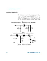
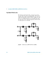
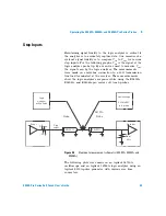
Equivalent Probe Loads
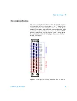
The following probe load models are based on in- circuit
measurements made with an Agilent 8753E 6 GHz network
analyzer and an Agilent 54750A TDR/TDT using a 50
Ω
test
fixture. The following schematic accurately models the probe
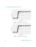
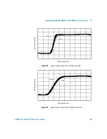
load out to 6 GHz. The figure on the following page shows
the agreement between measured impedance and this model.
PC board pads are not included.
Figure 28
Probe load model (E5402A, E5405A, and E5406A)
20K
Ω
Rtip1
1.17nH
L12
0.63nH
L11
C12
0.280pF
Rgnd1
0.5
Ω
Cm12
0.070pF
Rtrm1
75
Ω
.350pF
Cshnt1
20K
Ω
Rtip2
1.17nH
L22
0.63nH
L21
C22
0.280pF
Rgnd2
0.5
Ω
Rtrm2
75
Ω
.350pF
Cshnt2
D1
D0
+0.75V
+0.75V


