


Chapter 2
55
Overview of Functions
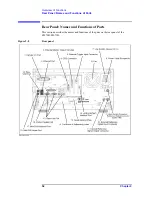
Rear Panel: Names and Functions of Parts
2.
Overvie
w
of Fun
ction
s
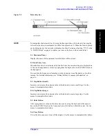
1. Handler I/O Port
The terminal to which an automatic machine (handler) used on a production line is
connected. For more on using the handler I/O port, see the Programmer’s Guide.
Connector type: 36-pin Ribbon (Centronics) connector
2. Ethernet Port
A terminal for connecting the E5070B/E5071B to a LAN (Local Area Network).
Connecting this instrument to a LAN enables you to access the hard disk drive of this
instrument from an external PC or to control this instrument by using SICL-LAN or telnet.
Connector type: 8-pin RJ-45 connector
Base standard: 10Base-T/100Base-TX Ethernet (automatic data rate selection)
3. External Monitor Output Terminal (Video)
A terminal to which an external color monitor (display device) can be connected. By
connecting a color monitor to this terminal, the same information shown on the LCD
screen of the main body can be displayed on an external color monitor.
Connector type: 15-pin VGA connector, female
4. GPIB Connector
General Purpose Interface Bus (GPIB). The connection of an external controller and other
devices through this connector allows you to configure an automatic measurement system.
For more on the automatic measurement system using GPIB, see the
Programmer’s Guide
.
5. External Trigger Input Connector (Ext Trig)
A connector to which external trigger signals are input. This connector detects the
downward transition from the HIGH state in TTL signals as the trigger signal. To use this
connector to generate a trigger, you must set the trigger source to the “external” side (key
operation:
-
Trigger Source
-
External
).
Connector type: BNC connector, female
6. Fan
The cooling fan for controlling the temperature inside the E5070B/E5071B. This fan
exhausts heated air from inside the analyzer to the outside.
7. Line Switch (Always ON)
Always keep this switch on (|).
CAUTION
Do not use this switch to turn off (
) the mains. Doing so may cause the analyzer to
fail.
For more information, see the description of the “1. Standby Switch” on page 31.
Summary of Contents for E5070B
Page 6: ......
Page 30: ...24 Contents ...
Page 34: ...28 Chapter1 Precautions Before contacting us ...
Page 286: ...280 Chapter6 Data Analysis Using the Equation Editor ...
Page 430: ...424 Chapter12 Optimizing Measurements Performing a Segment by Segment Sweep segment sweep ...
Page 538: ...532 Chapter15 Measurement Examples Executing Power Calibration ...
Page 634: ...628 AppendixB Troubleshooting Warning Message ...
Page 732: ...726 AppendixD Softkey Functions Trigger Menu ...
Page 740: ...734 AppendixE General Principles of Operation Data Processing ...
Page 760: ...754 AppendixF Replacing the 8753ES with the E5070B E5071B Comparing Functions ...


