background image

18

1


Installation

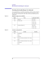
Mounting front handles/flanges for rackmount

Mounting rackmount kit (Option 1CM)

The rackmount kit is a kit that contains 2 flanges (side plates for securing) to mount the 
E5053A into the standard rack (width: 482.6 mm) of the EIA standard. Follow these steps 
to mount it, referring to the Figure 1-4.

Step 1.

Remove the trim strips (1) stuck to both the sides of the front panel (stuck to the frame).

Step 2.

Mount the flanges for rackmount (2) to both the sides of the front panel of the E5053A 
with the attached screws.

Step 3.

Remove the four legs on the bottom of the E5053A (pull up the part with the (

TAB


indication and slide it to the arrow direction).

Step 4.

Mount the E5053A into the rack. 

Mounting rackmount/handle kit (Option 1CP)

The rackmount/handle kit is a kit that contains both the flanges for rackmount and the front 
handles for the E5053A. Follow these steps to mount it, referring to the Figure 1-4.

Step 1.

Remove the trim strips (1) stuck to both the sides of the front panel (stuck to the frame).

Step 2.

Mount the front handles (3) and the flanges for rackmount (4) to both the sides of the front 
panel of the E5053A with the attached screws.

WARNING

Be sure to use both the front handles and the rack-mounting flanges at the same time. 
Do not attempt to install flanges or handles separately with the hardware provided, 
since this risks serious electrical damage to the instrument.

Step 3.

Remove the 4 legs on the bottom of the E5053A (pull up the part with the (

TAB

 indication 

and slide it to the arrow direction).

Step 4.

Mount the E5053A into the rack. 

Summary of Contents for E5053-90020

Page 1: ...highly sensitive microcircuits in your instrument ESD damage is most likely to occur as the test fixtures are being connected or disconnected Protect them from ESD damage by wearing a grounding strap...

Page 2: ...f the instrument If you continue to operate without repairing the instrument there is a potential fire or shock hazard for the operator Instrument operates abnormally Instrument emits abnormal noise s...

Page 3: ...lerbescheinigung GER AUSCHEMISSION LpA 70 dB am Arbeitsplatz normaler Betrieb nach DIN 45635 T 19 Manufacturer s Declaration ACOUSTIC NOISE EMISSION LpA 70 dB operator position normal operation per IS...

Page 4: ...owing applicable European Directives and carries the CE marking accordingly The Low Voltage Directive 73 23 EEC amended by 93 68 EEC The EMC Directive 89 336 EEC amended by 93 68 EEC To obtain Declara...

Page 5: ...quipment is POLLUTION DEGREE 2 INDOOR USE product This equipment is tested with stand alone condition or with the combination with the accessories supplied by Agilent Technologies against the requirem...

Page 6: ......

Page 7: ...ide Third Edition FIRMWARE REVISIONS This manual applies directly to instruments that have the E5052A firmware revision A 02 00 and later For additional information about firmware revisions see Append...

Page 8: ...ther countries licensed exclusively through X Open Company Limited Portions Copyright 1996 Microsoft Corporation All rights reserved Copyright 2005 2007 Agilent Technologies Manual Printing History Th...

Page 9: ...ents are to be confirmed by the builder of the system Ground the Instrument To avoid electric shock the instrument chassis and cabinet must be grounded with the supplied power cable s grounding prong...

Page 10: ...the instrument manual Alternating current Direct current On Supply Off Supply In position of push button switch Out position of push button switch A chassis terminal a connection to the instrument s...

Page 11: ...ilities of other International Standards Organization members Exclusive Remedies The remedies provided herein are Buyer s sole and exclusive remedies Agilent Technologies shall not be liable for any d...

Page 12: ...screen labeled Sample which can be selected executed by clicking menu button box or tab may be omitted key Indicates a hardkey key on the front panel or external keyboard labeled Sample key may be omi...

Page 13: ...ly 22 2 Overview of Product About This Product 24 Names and Functions of Parts 25 Front Panel 25 Rear Panel 27 3 Connecting Devices to E5052A for Operation Connecting E5052A and E5053A 30 Required Dev...

Page 14: ...8 Contents...

Page 15: ...9 1 Installation 1 Installation This chapter provides information on how to set up the Agilent E5053A microwave downconverter...

Page 16: ...ts of the package for mechanical damage or defects Step 3 Check the contents of the shipment using Table 1 1 and Figure 1 1 to see if all your specified options are complete Step 4 If you detect any o...

Page 17: ...information as in the User s Guide The xx in the part number is a number that is incremented each time a revision is made with 00 regarded as the first edition The latest edition comes with the produc...

Page 18: ...12 1 Installation Incoming inspection Figure 1 1 Accessories...

Page 19: ...s CAUTION The above environmental requirements are not intended for the specifications and measurement accuracy of the analyzer but for the operating environment of the analyzer Table 1 2 Temperature...

Page 20: ...to satisfy the specifications and measurement accuracy of the product refer to the Specifications and supplemental performance characteristics Chapter in the User s Guide When the temperature around t...

Page 21: ...sures Providing space to disconnect the power cable s plug As described in Cutting power supply on page 22 the disconnecting device the device to cut the supply of power of the E5053A is the plug of t...

Page 22: ...ent system Option 1CM without handles Option 1CP with handles Table 1 4 Handle rack options for the E5053A Option Name Agilent part number 1CN Handle kit 5063 9227 1CM Rackmount kit 5063 9214 E5053 61...

Page 23: ...to mount it referring to the Figure 1 4 Step 1 Remove the trim strips 1 stuck to both the sides of the front panel stuck to the frame Step 2 Mount the front handles 3 to both the sides of the front pa...

Page 24: ...53A into the rack Mounting rackmount handle kit Option 1CP The rackmount handle kit is a kit that contains both the flanges for rackmount and the front handles for the E5053A Follow these steps to mou...

Page 25: ...wing specifications UL CSA type Slo Blo 5 20 mm miniature fuse 3A 250V Agilent part number 2110 1017 Spare fuses are available from Agilent Technologies sales offices To check or replace the fuse disc...

Page 26: ...azards Step 1 Check the power cable you use for damage WARNING Never use a power cable that may be damaged You may get an electrical shock Step 2 Connect the attached power cable between the power cab...

Page 27: ...1 21 Installation Power supply and fuse 1 Installation Figure 1 6 Power cable options...

Page 28: ...s pulled up NOTE To turn OFF the E5053A under normal conditions press the line switch Under normal conditions never disconnect the power cable to cut the power supply to the power cable receptacle on...

Page 29: ...23 2 Overview of Product 2 Overview of Product This chapter presents an overview of the E5053A microwave downconverter...

Page 30: ...is Product The Agilent E5053A is a microwave downconverter associated with the E5052A signal source analyzer The E5053A expands the maximum frequency of the E5052A to 26 5 GHz Operating the E5053A req...

Page 31: ...parts are described below Figure 2 1 Front Panel 1 Line switch Turns on off the E5053A 2 IF LO channel 2 input output port When using an external mixer disconnect this port 3 IF LO channel 1 input out...

Page 32: ...mm female connector is used CAUTION Do not apply a DC voltage greater than 0 V to the connection port In particular there is the risk of the capacitor remaining charged Connect the measurement sample...

Page 33: ...he E5052A signal source analyzer to the USB port is not supported 2 External reference signal input connector channel 1 channel 2 Ref In A reference signal input connector in order to phase lock the E...

Page 34: ...evice side of the cable serves as the disconnecting device device that cuts off power supply of the E5053A When the power supply must be cut off to avoid danger such as eclectic shock pull out the pow...

Page 35: ...ecting Devices to E5052A for Operation 3 Connecting Devices to E5052A for Operation This chapter describes how to connect the E5052A signal source analyzer and the E5053A microwave downconverter for o...

Page 36: ...with the E5053A Agilent part number E5053 61621 E5053 61622 USB cable supplied with the E5053A Agilent part number 8121 0770 BNC m BNC m cable 61 cm supplied with the E5053A Agilent part number 8120...

Page 37: ...USB host port both front and rear or turn them on off during measurement Turning on Power After connecting the E5052A and the E5053A follow these steps to turn on the power Step 1 Turn on the E5053A S...

Page 38: ...ecting Devices to E5052A for Operation Basic Operation Basic Operation For information on operation see the Measurement Using the E5053A and a External Mixer chapter in the E5052A Signal Source Analyz...

Page 39: ...33 4 Specifications and Supplemental Information 4 Specifications and Supplemental Information This chapter provides specifications and supplemental information for the Agilent E5053A...

Page 40: ...ct warranty This information is denoted as either typical or nominal Specification spec Warranted performance Specifications include guardbands to account for the expected statistical performance dist...

Page 41: ...el 23 dBm nominal LO Output Frequency Range 3 025 G to 10 025 GHz Resolution 50 MHz Frequency Accuracy 1 1 When the LO is locked to the built in 10 MHz reference of the E5053A 10 ppm 23 C 5 C Output L...

Page 42: ...t Frequency 10 MHz 50 Hz typical Output Level 2 5 dBm 3 dB typical USB USBTMC 1 interface Port Connector Type Universal Serial Bus jack Type B configuration 4 contacts inline female provides connectio...

Page 43: ...nsitivity 23 C 5 C Input Frequency Offset from carrier Hz 1 10 100 1 k 10 k 100 k 1 M 10 M 40 M 3 GHz spec 110 5 116 5 113 5 127 5 140 0 140 0 typ 49 5 79 5 94 5 114 5 120 5 117 5 131 5 144 0 144 0 6...

Page 44: ...0 AM IEC 61000 4 4 1995 EN 61000 4 4 1995 1 kV power 0 5 kV Signal IEC 61000 4 5 1995 EN 61000 4 5 1995 0 5 kV Normal 1 kV Common IEC 61000 4 6 1996 EN 61000 4 6 1996 3 V 0 15 80 MHz 80 AM IEC 61000 4...

Page 45: ...erature 10 C to 40 C Error Corrected Temperature Range 23 C 5 C with 1 C deviation from calibration temperature Humidity 20 RH to 80 28 C non condensing Altitude 0 to 2 000 m 0 to 6 561 feet Vibration...

Page 46: ...40 Chapter4 Specifications and Supplemental Information General Information Figure 4 3 Dimensions rear view in millimeters nominal Figure 4 4 Dimensions side view in millimeters nominal...

Page 47: ...41 5 Information on Maintenance 5 Information on Maintenance This chapter explains the measures you should take to maintain the Agilent E5053A...

Page 48: ...ificantly affect the accuracy in measurements in the RF range Always pay attention to the following precautions Always keep the connectors free from stains and dust Do not touch the contact surface on...

Page 49: ...calibration of the unit by our Service Center send only the E5053A main unit without any installed option you may have ordered Unless specifically instructed it is not necessary to send accessories an...

Page 50: ...44 Chapter5 Information on Maintenance Cautions Applicable to Requesting Repair Replacement Regular Calibration etc...

Page 51: ...ual Changes A Manual Changes This appendix contains the information required to adapt this manual to versions or configurations of the E5053A manufactured earlier than the current printing date of thi...

Page 52: ...hnologies uses a two part ten character serial number that is stamped on the serial number plate Figure A 1 The first five characters are the serial prefix and the last five digits are the suffix Figu...

Page 53: ...Internal Reference Signal Output Connector 28 M manual changes 45 manual printing history 2 N names and functions of parts 25 nominal definitions 34 O operating environment 13 P power supply checking...

Page 54: ...1 800 452 4844 fax 1 888 900 8921 Canada Test and Measurement Call Center tel 1 877 894 4414 fax 1 888 900 8921 China tel 800 810 0189 fax 800 820 2816 Europe tel 31 20 547 2323 fax 31 20 547 2390 Jap...

Reviews: