


Chapter 4
139
Basic Digital Operation
Using Waveform Markers
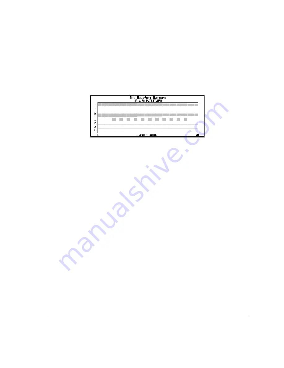
8. Press
Apply To Waveform
>
Return
.
This causes the marker to occur on every other point (one sample point is skipped) within the marker point
range, as shown below.
One application of the skipped point feature is the creation of a clock signal as the auxiliary output.
Controlling Markers in a Waveform Sequence (Dual ARB Only)
In a waveform segment, an enabled marker point generates an auxiliary output signal that is routed to the
rear-panel event connector (described in
“Rear Panel Overview” on page 37
) corresponding to that marker
number. For a waveform sequence, you enable or disable markers on a segment-by-segment basis; this
enables you to output markers for some segments in a sequence, but not for others. Unless you change the
marker settings or cycle the power, the setting remains the same for the next loaded sequence.
As You Create a Waveform Sequence
After you select the waveform segments to create a waveform sequence, and
before
you name and save the
sequence, you can enable or disable each segment’s markers independently. Enabling a marker that has no
marker points (
) has no effect on the auxiliary outputs.
1. Select the waveform segments (
2. Toggle the markers as desired:
a. Highlight the first waveform segment.
b. Press
Enable/Disable Markers
.
c. As desired, press
Toggle Marker 1
,
Toggle Marker 2
,
Toggle Marker 3
, and
Toggle Marker 4
.
Toggling a marker that has no marker points (
) has no effect on the auxiliary outputs.
An entry in the
Mkr
column (see figure below) indicates that the marker is enabled for that segment;
no entry in the column means that all markers are disabled for that segment.
d. In turn, highlight each of the remaining segments and repeat
3. Press
Return
.
Viewing markers is described on
Summary of Contents for E4428C
Page 22: ...Contents xxii ...
Page 224: ...200 Chapter 4 Basic Digital Operation Creating and Using Bit Files ...
Page 228: ...204 Chapter 5 AWGN Waveform Generator Configuring the AWGN Generator ...
Page 229: ...205 6 Analog Modulation ...
Page 276: ...252 Chapter 7 Digital Signal Interface Module Operating the N5102A Module in Input Mode ...
Page 286: ...262 Chapter 8 Bluetooth Signals Turning On a Bluetooth Signal ...
Page 330: ...306 Chapter 9 BERT Verifying BERT Operation ...
Page 366: ...342 Chapter 10 CDMA Digital Modulation IS 95A Modulation ...
Page 394: ...370 Chapter 12 Multitone Waveform Generator Applying Changes to an Active Multitone Signal ...
Page 468: ...444 Chapter 15 W CDMA Digital Modulation for Component Test W CDMA Frame Structures ...
Page 667: ...643 18 Troubleshooting ...
Page 700: ...Index 676 Index ...