


Chapter 4
189
Basic Digital Operation
User-Defined I/Q Maps
Entering I and Q Values
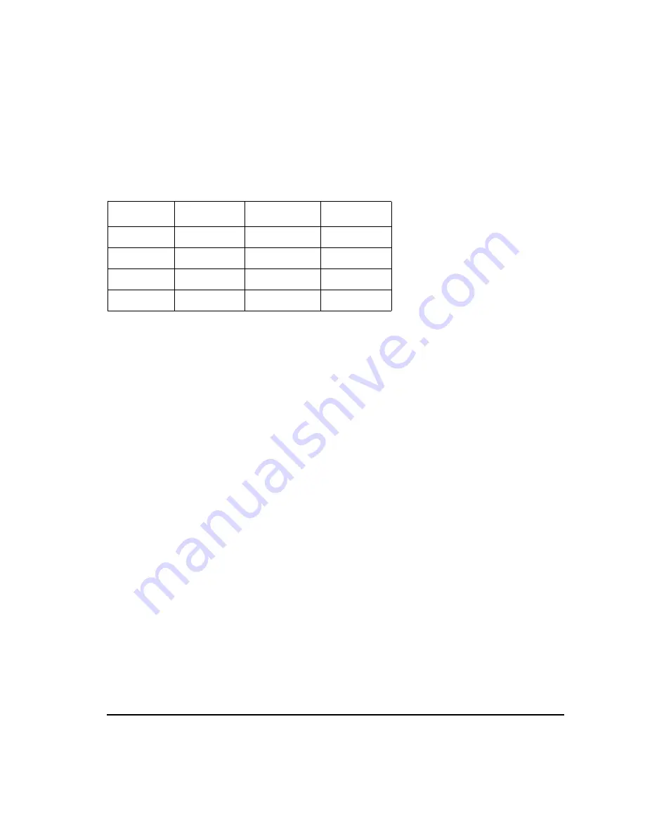
Enter the I and Q values listed in the following table.
1. Press
.5
>
Enter
.
2. Press
1
>
Enter
.
3. Enter the remaining I and Q values.
As the I value updates, the highlight moves to the first Q entry (and provides a default value of 0), and an
empty row of data appears below the first row. As the Q value updates, and the highlight moves to the next I
value. As you press the numeric keys, the numbers display in the active entry area. If you make a mistake,
use the backspace key and then retype.
Also note that
0.000000
appears as the first entry in the list of
Distinct Values
, and that
0.500000
and
1.000000
are listed as the distinct values.
Displaying the I/Q Map
1. Press
Display I/Q Map
An I/Q map generated using the current values in the
I/Q Values
table editor is displayed.
The map in this example has four symbols. The map uses the following
four
unique values: 0.5, 1.0,
−
0.5, and
−
1.0 to create the four symbols. It is not the number of values that defines how many symbols
a map has, but how those values are combined.
2. Press
Return
.
When the contents of a table editor have not been stored,
I/Q Values (UNSTORED)
appears on the
display. Follow the instructions in the next section to store the custom I/Q table.
Symbol
Data Bits
I Value
Q Value
0
0000
0.500000
1.000000
1
0001
−0.500000
1.000000
2
0010
0.500000
−1.000000
3
0011
−0.500000
−1.000000
Summary of Contents for E4428C
Page 22: ...Contents xxii ...
Page 224: ...200 Chapter 4 Basic Digital Operation Creating and Using Bit Files ...
Page 228: ...204 Chapter 5 AWGN Waveform Generator Configuring the AWGN Generator ...
Page 229: ...205 6 Analog Modulation ...
Page 276: ...252 Chapter 7 Digital Signal Interface Module Operating the N5102A Module in Input Mode ...
Page 286: ...262 Chapter 8 Bluetooth Signals Turning On a Bluetooth Signal ...
Page 330: ...306 Chapter 9 BERT Verifying BERT Operation ...
Page 366: ...342 Chapter 10 CDMA Digital Modulation IS 95A Modulation ...
Page 394: ...370 Chapter 12 Multitone Waveform Generator Applying Changes to an Active Multitone Signal ...
Page 468: ...444 Chapter 15 W CDMA Digital Modulation for Component Test W CDMA Frame Structures ...
Page 667: ...643 18 Troubleshooting ...
Page 700: ...Index 676 Index ...