


Performance Tests
Output Standing Wave Ratio (SWR) Test
Agilent E4418B/E4419B Service Guide
2-25
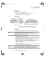
Equipment
• Test power meter: Agilent 432A.
• Thermistor mount: Agilent 478A option H75 or H76.
• Digital voltmeter (DVM): Agilent 3458A.
Test Setup
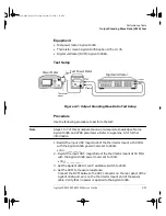
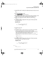
Figure 2-7: Output Standing Wave Ratio Test Setup
Procedure
Use the following procedure to perform the test:
Note
Steps 1 to 7 of this procedure require pre-requisite knowledge of some
Agilent 432A and 478A parameters. Refer to Appendix A for further
information.
1. Record the input VRC magnitude of the thermistor mount at 50 MHz
with the Agilent 432A power meter set to 200
Ω
:
• |R
1
| ___________
2. Record the input VRC magnitude of the thermistor mount at 50 MHz
with the Agilent 432A power meter set to 100
Ω
:
• |R
2
| ___________
3. Set the Agilent 432A mount resistance switch to 200
Ω
.
4. Set the DVM to measure resistance:
Connect the DVM between the VRF connector on the rear panel of the
Agilent 432A and pin 1 on the thermistor mount end of the sensor
cable. Verify that no power is applied to the Agilent 432A.
Power Meter
V
RF
V
comp
Thermistor
mount
Digital Voltmeter
Power
ref
+ input
Test Power Meter
- input
4402serv.book Page 25 Tuesday, October 14, 2003 3:18 PM
Summary of Contents for E4418B
Page 19: ...1 Specifications 4402serv book Page 1 Tuesday October 14 2003 3 18 PM ...
Page 37: ...2 Performance Tests 4402serv book Page 1 Tuesday October 14 2003 3 18 PM ...
Page 69: ...3 Adjustments 4402serv book Page 1 Tuesday October 14 2003 3 18 PM ...
Page 81: ...4 Theory of Operation 4402serv book Page 1 Tuesday October 14 2003 3 18 PM ...
Page 95: ...5 Replaceable Parts 4402serv book Page 1 Tuesday October 14 2003 3 18 PM ...
Page 119: ...6 Troubleshooting 4402serv book Page 1 Tuesday October 14 2003 3 18 PM ...


