background image

Aurora

Presto

—User Guide

3-24

481801

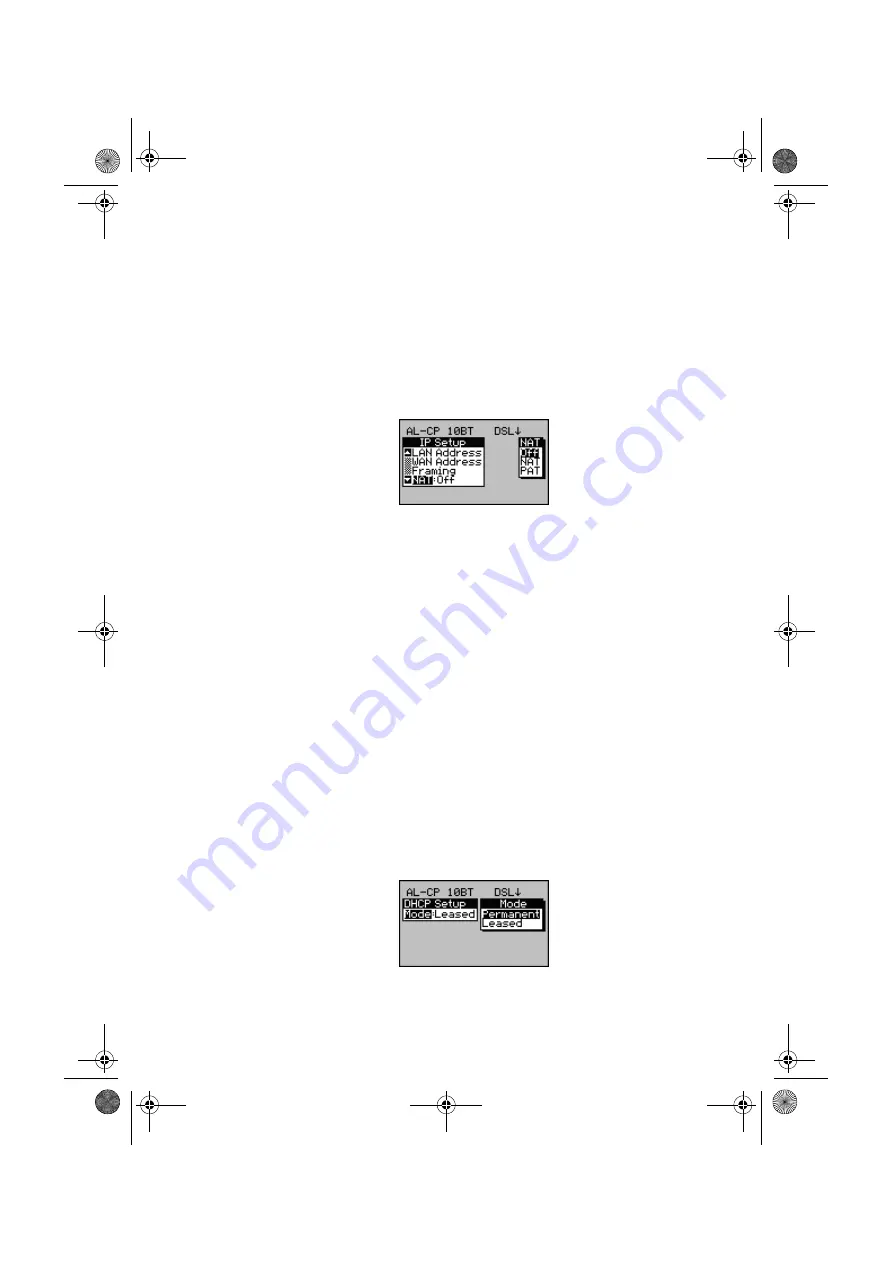
The 

PAT

 option (also known as NAPT Network Port 

Address Translation) is used when you want to connect to 
several devices.

These options are only available if you have set up the 

IP 

Mode

 to 

Routed

.

-1-

From the

 IP Setup

 screen select

 NAT 

and press 

ENTER


to display the 

NAT

 options.

-2-

Choose 

NAT

 or 

PAT

 depending on the connection.

Choose 

Off 

to disable the NAT option.

Setting up the DHCP 

(Dynamic Host Configuration Protocol)

This option is only available if you have set up the 

IP Mode


to 

Routed.

The DHCP option enables 

Aurora

Presto

, when configured 

as a Golden Router, to allocate IP addresses to the LAN 
dynamically so that an address can be reused when a device 
is no longer connected to the network.

The DHCP pool is the number of local IP addresses that the 
server can distribute. The limit is 10 on 

Aurora

Presto

.

DHCP allocates a lease to each IP address. This lease can be 
unlimited (

Permanent

), set for a length of time set up by 

the user (

Leased

).

-1-

Select

 DHCP Setup

 from the

 IP Setup

 screen to 

display the 

DHCP Setup

 screen.

481801-7.book  Page 24  Thursday, May 23, 2002  10:46 AM

Summary of Contents for AuroraPresto

Page 1: ...481801 Issue 7 05 02 AuroraPresto User Guide aurora Presto 481801 7 book Page 1 Thursday May 23 2002 10 46 AM...

Page 2: ...ales and service contact information in this manual may be out of date The latest service and contact information for your location can be found on the Web at http www agilent com find assist If you d...

Page 3: ...yright and all restrictions on reproduction and use apply to all media in which this information may be placed Agilent Technologies pursues a policy of continual product improvement and reserves the r...

Page 4: ...roraPresto 1 8 How AuroraPresto fits Together 1 8 Safety Advice 1 9 Looking after AuroraPresto 1 10 A Look at AuroraPresto 1 11 Summary of the Main Features 1 12 The Keypad 1 13 Understanding the LEDs...

Page 5: ...2 15 Displaying Interface Cards or Modules 2 16 Entering Alphanumeric Information 2 16 Adding or Deleting Characters 2 17 Saving the String and Exiting 2 17 Chapter 3 Setting up AuroraPresto 3 1 Sett...

Page 6: ...figurations Files to AuroraPresto 3 50 Uploading Configuration Files from AuroraPresto 3 50 Uploading Sessions from AuroraPresto to a PC 3 51 During the Transfer 3 51 Chapter 4 Testing with AuroraPres...

Page 7: ...ting Up the TDR Tester 4 26 Running a TDR Test 4 28 Viewing the TDR Test Results Graph 4 29 Load Coil Tests 4 31 Running a Load Coil Test 4 32 G SHDSL Physical Layer Test 4 32 Section 4 DSL Layer Test...

Page 8: ...Stats 4 83 Displaying the LAN Global Stats 4 83 Displaying the LAN Connection Stats 4 84 IP Ping Test 4 85 Setting up the IP Ping Test 4 86 Setting up the Route Trace Options 4 88 Starting a Route Tra...

Page 9: ...AuroraPresto Specifications 7 2 Telecommunications Standards 7 2 User Interface 7 2 Physical Environmental 7 3 Power supplies 7 4 Memory Capacity 7 4 Interface Specifications 7 4 ADSL line 7 4 10 Base...

Page 10: ...2 Setup 1 2 Tests 1 5 Appendix 2 ADSL Status Messages Vendor Codes 2 1 Abbreviations Used 2 3 ADSL Trace Message Definitions 2 4 G SHDSL Trace Message Definitions 2 6 Vendor Codes 2 6 Appendix 3 Glos...

Page 11: ...Issue 7 05 02 1 Chapter 1 Welcome to AuroraPresto Contents Section 1 About the User Guide 1 3 Section 2 Introducing Aurora Aurora Aurora AuroraPresto 1 7 481801 7 book Page 1 Thursday May 23 2002 10...

Page 12: ...gure troubleshoot and maintain equipment on xDSL lines Tip If you are a new user read through Chapters 1 and 2 of this Guide for the basic information you need to get started When you are more familia...

Page 13: ...uration and may include features that you did not purchase Intended Readers This Guide is intended for all users of AuroraPresto normally first line and second line installation and maintenance person...

Page 14: ...roraPresto along with information to assist equipment purchasers Appx 1 Diagrams to help you navigate through the menu structure Appx 2 ADSL Line Status Messages Appx 3 A glossary of technical terms u...

Page 15: ...urrent menu or option list Press n Press and hold Shift while pressing the specified key n then release both keys Highlight Use the arrow keys to move the cursor bar over an option ADSL applies specif...

Page 16: ...1 6 481801 STU R applies specifically to G SHDSL Remote Terminating Units xTU C applies to all Central Office Terminating Units xTU R applies to all Remote Terminating Units 481801 7 book Page 6 Thurs...

Page 17: ...and lines G SHDSL equipment and lines the route through the network via ATM Asynchronous Transfer Mode switches and DSL equipment the integrity of a link and the quality of service the availability a...

Page 18: ...its Together AuroraPresto consists of a base unit into this base unit up to four interface cards may be fitted For details see About the Interface Cards on page 1 17 Your AuroraPresto is fitted with t...

Page 19: ...e Avoid using the tester during an electrical storm there is a remote risk of electric shock by lightning Use only the batteries supplied for the unit These are described in Chapter 6 and in the power...

Page 20: ...and 30 C You can store the unit safely between 25 C and 70 C very wet conditions AuroraPresto is weather resistant but not waterproof You can use it in light rain when held vertically but you should n...

Page 21: ...onnectors see The interface connectors panel on page 1 18 LCD Water Resistant Cover Belt Hook External Power Supply Battery Charger LEDs Water Resistant Cover Serial Port Connector Keypad Interface Co...

Page 22: ...r AuroraPresto s RS232 serial port which links to a terminal printer PC or VDU for output of protocol decodes and test results LEDs Six Light Emitting Diodes giving instant information on line status...

Page 23: ...e an arrow To move several steps in the same direction hold down the arrow Enter Press this key to choose a highlighted menu item or setting or to start an operation Esc Use this key to exit from menu...

Page 24: ...e Adjusts the screen contrast Switches the screen backlight on and off Adjusts the volume of the loudspeaker Displays context sensitive Help Shows the current configuration of your AuroraPresto Not us...

Page 25: ...ecks on the status of the line BERT Indicates BERT synchronisation S Y N C A L A R M D S L E X T B E R T B A T DSL Activity see LED Information Table DSL ALARM see LED Information Table DSL SYNC Indic...

Page 26: ...charged BERT Red Flashing Red Off BERT SYNCHRONISATION BERT error BERT is not synchronised No BERT activity or no errors EXT Off Green EXTERNAL DATA PORT ACTIVITY No data port activity Transmit or Rec...

Page 27: ...Technologies representative At present the following interface cards and modules are available G SHDSL Interface STU R and STU C ADSL Interface over POTS ATU R and ATU C ADSL Interface over ISDN ATU R...

Page 28: ...ies to do so Connector safety The connectors on AuroraPresto conform to EN60950 safety status classifications as shown in the following table Connection with other equipment should be made such that t...

Page 29: ...ins battery charger eliminator appropriate to the country of use For ADSL line interface RJ11 to RJ11 straight RJ11 to RJ11 crossover For G SHDSL Line Interface RJ45 to RJ11 straight RJ45 to RJ45 stra...

Page 30: ...net or ATMF 25 6 Interface RJ45 to RJ45 straight Ethernet ATM 25 RJ45 to RJ45 crossover Ethernet RJ45 to RJ45 crossover ATM optional Other cables are supplied on request as optional accessories 481801...

Page 31: ...hapter 2 Getting Started Contents Section 1 Preparing to Use Aurora Aurora Aurora AuroraPresto 2 3 Section 2 Using the Menus and Windows 2 11 Section 3 Basic Operations 2 15 481801 7 book Page 1 Thurs...

Page 32: ...ly this chapter is divided into the following sections Section 1 Preparing to Use AuroraPresto on page 2 3 Section 2 Using the Menus and Windows on page 2 11 Section 3 Basic Operations on page 2 15 Th...

Page 33: ...ns electricity supply Then you need to connect to the interfaces on which you intend to test Tip You will find more information about the power sources in Chapter 6 For details of the required voltage...

Page 34: ...Connect the other end of the cable to the equipment you want to test xDSL Connections The following diagrams show all the points on the xDSL 2 wire connections where you can connect and test using Aur...

Page 35: ...e Ethernet port for connecting to and simulating DTE operating in Golden Modem Mode downloading software ATMF25 6 AuroraPresto is fitted with a standard ATMF25 6 ATM25 port You can use the ATM25 port...

Page 36: ...hernet port See Installing AuroraExchange on the PC on page 3 42 Note The serial ports on both devices must be set up in the same way For details on how to change the configuration of AuroraPresto s s...

Page 37: ...ting For more details about the Select Test Mode menu see The Select Test Mode Menu on page 2 11 Changing the Appearance of the Screen You can make the display easier to read in different lighting con...

Page 38: ...cklight goes off see Changing the Basic Configuration on page 3 7 Removing Replacing the Belt Hook AuroraPresto has a removable belt hook attached to the battery pack cover at the back of the unit You...

Page 39: ...holder by sliding it back in and pushing down to secure it in place Warning Belt hook bolt Always keep the bolt in its holder If you lose it you will not be able to replace the belt hook and the case...

Page 40: ...ge 2 8 2 Replace the hook by placing it in the socket at the top of the battery pack cover with the opening pointing towards the back of the unit Line up the bolt holes in the hook with the holes in t...

Page 41: ...up box listing the settings or values you can choose for the item you have selected For example The Select Test Mode Menu The Select Test Mode menu leads to all AuroraPresto s sub menus and options fr...

Page 42: ...are more options than can fit on a single screen When a scroll bar is displayed you can use the following keys to move through the items more quickly to highlight the first item in the menu press to h...

Page 43: ...screen For example Press F1 Del Exiting from a Menu or Option Window In all menus and sub menus when you press ENTER to select a menu item AuroraPresto automatically displays the sub menu or screen ap...

Page 44: ...mple when you are entering a Session Name an entry window is displayed Only one of the windows is active at a time The active window is indicated by a shadow effect for example To change the active wi...

Page 45: ...mes to identify stored test results Adjusting the Volume To switch the loudspeaker on or off press the key located on the right hand side above the screen The default is on Note When you switch the lo...

Page 46: ...cards fitted in your AuroraPresto are displayed Entering Alphanumeric Information When performing certain tasks you need to enter a string of alphanumeric characters For example when entering a Hot k...

Page 47: ...the string by switching to the edit window and moving the cursor In the edit window to move quickly from the last character to the first press Home To move from the first to the last character press E...

Page 48: ...AuroraPresto User Guide 2 18 481801 481801 7 book Page 18 Thursday May 23 2002 10 46 AM...

Page 49: ...ora AuroraPresto Using Hot Keys 3 2 Changing the Basic Configuration 3 7 General Settings System Setup 3 31 Checking the Current Setup of Aurora Aurora Aurora AuroraPresto 3 41 Installing New Software...

Page 50: ...w to set up AuroraPresto to test on DSL change general settings such as the display language configure the serial port configure AuroraPresto with default settings download new software Note For Bit E...

Page 51: ...R I ADSL over ISDN operation 4 ADI ATU R P ADSL over POTS operation You can use the Hot Key options to retrieve preset configurations or profiles retrieve custom configurations or profiles save the cu...

Page 52: ...ming a Hot Key Use this to enter a name for the Hot Key you have selected Notes When you assign a name to a Hot Key AuroraPresto records that the Hot Key has a name assigned to it The name is not stor...

Page 53: ...e 2 16 4 Press F4 OK to accept the name entry and return to the Hot Keys screen The Hot Key name you have entered is displayed Storing a Hot Key Note You must name the Hot Key before you can store it...

Page 54: ...rofile for testing 1 From the Hot Keys menu use the UP and DOWN keys to select the Hot Key you want to load and press ENTER OR use the keypad to enter the Hot Key number For example to load Hot Key 15...

Page 55: ...Notes You can access the Setup menus from the Status screen Press 5 to display the Status screen from any Setup menu See Checking the Current Setup of AuroraPresto on page 3 41 You can also access the...

Page 56: ...e to set up Dst Destination IP Address Max TTL Time to Live and Timeout IP Use to set up the IP Options PPP Use to set up PPP Type Authentication Method Password User and Tracer Configuring the Serial...

Page 57: ...d rate from the Serial Setup menu to display a list of possible rates in kilobits per second 2 Highlight your choice and press ENTER Setting the character length of serial port data You need to specif...

Page 58: ...l Setup menu 2 Highlight the option you require and press ENTER The options are Including stop bits Stop bits are the last bits sent in asynchronous transmission to indicate that the message is comple...

Page 59: ...s receiving from AuroraPresto 1 Select XON XOFF from the Comms Tracer menu to display the options 2 Choose either On or Off and press ENTER Note It is usually best to set XON XOFF to On on both Aurora...

Page 60: ...choose Auto AuroraPresto automatically chooses the correct regional setting Training Use to set the modem training to Automatic or Manual Up Nm Attn ADI ATU R only Use to enable or disable the Upstre...

Page 61: ...Maximum Fast Bit Rate Min IBR kbps Minimum Interleaved Bit Rate Max IBR kbps Maximum Interleaved Bit Rate Downstream only Max PSD Maximum Power Spectral Density The maximum ATU C downstream power Trac...

Page 62: ...Trace Route Options Your AuroraPresto may not have the Trace Route option For details contact your Agilent Technologies representative 1 From the Select Test Mode screen press F4 Setup to display the...

Page 63: ...ecessary Timeout ms Use this to set up the time to wait for a response from a specified router before terminating the test Enter a value between 500 and 5000ms Setting up the IP Options The IP Interne...

Page 64: ...Frame type Ethernet encapsulation method IP operation mode and IP Header compression NAT Use to set up the Network Address Translation settings DHCP Use to set up the Dynamic Host Configuration Protoc...

Page 65: ...are using an Ethernet connection Choose a VC if you are using an ADSL connection 3 Press ENTER to save the changes 4 Press ESC to exit the IP Setup screen Setting up the LAN Address This option is us...

Page 66: ...The dot is entered automatically You can enter a new number or accept the current setting 3 Press ENTER Note The above options consist of 4 groups of 3 digits divided by a dot The maximum number you c...

Page 67: ...dress DNS Use this to set up the Domain Name Server Note Origin must be set to Specify before you can enter a Src Source IP Address Note The above options consist of 4 groups of 3 digits divided by a...

Page 68: ...the source address is set to Src Acquire Mode in the IP Setup menu To display the actual IP Address supplied press 5 to display the Status screen 3 Press ENTER to accept the entry Note AuroraPresto wi...

Page 69: ...tting 3 Press ENTER Note The above options consist of 4 groups of 3 digits divided by a dot The maximum number you can enter in each group is 255 Setting up IP Framing 1 Select Framing from the IP Set...

Page 70: ...Note You can set up the IP options from the Select Tests screen Setting up the IP Ping Test on page 4 86 Setting up the IP Encapsulation 1 Select IP Encap from the Framing Setup menu A screen similar...

Page 71: ...raming Setup menu A screen similar to the following is displayed 2 Choose On to enable header compression OR Off to disable header compression depending on how the network is set up 3 Press ENTER to a...

Page 72: ...This option is only available if you have set up the IP Mode to Routed The DHCP option enables AuroraPresto when configured as a Golden Router to allocate IP addresses to the LAN dynamically so that...

Page 73: ...rates the network address from the device address See Entering the Source IP address Mask IP address on page 3 18 for details on entering the Mask IP address Lease Time This option is only available w...

Page 74: ...ease to run The maximum time you can enter is 99 59 59 3 Press ENTER to accept the entry Setting up PPP Options The PPP Option is only available if your organisation has purchased this option For deta...

Page 75: ...Authentication method PAP etc User Use this to set up a User Name for a PPP session Pswd Use this to set up a password for a PPP session if applicable Tracer Use to set up the display of events for A...

Page 76: ...dentifiers and VCIs Virtual Channel Identifiers on page 4 52 Setting Up the PPP Mode 1 From the PPP Setup menu choose Type and press ENTER to display the following screen 2 Choose Client or Server Not...

Page 77: ...uthentication Method 1 Select Authentication from the PPP Setup menu A screen similar to the following is displayed 2 Choose PAP Password Authentication Protocol or CHAP Challenge Handshake Authentica...

Page 78: ...ion on page 2 16 for information on entering alphanumeric information 3 Press F4 OK to continue Setting up the Tracer 1 From the PPP Setup menu select Tracer and press ENTER A screen similar to the fo...

Page 79: ...play the Main Setup screen Select System Setup to display the following Auto power off The time delay before AuroraPresto switches off to save the battery LCD Backlight The time delay before the scree...

Page 80: ...ve power if no tests are in progress and no keys have been pressed after a certain length of time To choose the time delay before AuroraPresto switches off 1 From the Select Test Mode menu press F4 Se...

Page 81: ...Highlight your choice and press ENTER to close the option window 3 Press ESC to save your selection and close the System Setup menu Changing the Date Time on the Internal Clock AuroraPresto has an int...

Page 82: ...of Operation AuroraPresto can cater for regional variations in ADSL operations You need to identify the country in which you are using your AuroraPresto it then automatically changes its settings to t...

Page 83: ...the language you wish to use and press ENTER to close the option window 3 Press ESC to save your selection and close the System Setup menu Returning to the Factory Defaults Note After performing a So...

Page 84: ...resets and loads the factory defaults This takes a few seconds Note When you return to the factory defaults you reset all the settings back to their original values that is the way they were when you...

Page 85: ...bles list AuroraPresto s factory default setting System Settings Auto Power Off Off Speaker Volume Off Country UK Language English Serial Comms Baud Rate 38400 Data Bits 8 Parity None Stop Bits 1 XON...

Page 86: ...3 38 481801 Modem Settings Type None Mode Auto Tracer Off ATM Settings VP1 8 VP2 8 VP3 8 VP4 8 VC1 35 VC2 17 VC3 18 VC4 19 VC Mode Disable VC TX Rate All 0 except VC1 25 481801 7 book Page 38 Thursda...

Page 87: ...x Tx Threshold Enabled Pattern 2047 p r Invert Pattern Off Duration 1 hour VPI 0 VCI 20 DSL BW 100 IP Ping Settings Src 000 000 000 000 Dst 000 000 000 000 Msk 000 000 000 000 Pings 10 Timeout 2000 Le...

Page 88: ...Route Src 000 000 000 000 Msk 255 255 255 000 Max TTL 10 Timeout 5000 IP Settings Mode Bridged IP Address Settings Src 000 000 000 000 Msk 000 000 000 000 IP Framing Settings IP Type DIX IP Encap VC M...

Page 89: ...To display the Status screen from any menu or screen 1 Press 5 2 Select the option you want to display 3 Press ESC to return to the Status screen OR G SHDSL Physical Settings Mode Auto Training Manua...

Page 90: ...stalled on a PC running Windows 95 98 or NT Caution If AuroraPresto loses power while software is being downloaded the tester may be damaged We recommend that you connect AuroraPresto to an external p...

Page 91: ...e settings with the exception of the Source IP Address Src For Software Version 1 05 or earlier the DGW Msk and IP Type on AuroraPresto and the PC must have the same settings See Setting up the IP Add...

Page 92: ...software version press 5 For details see Checking the Current Setup of AuroraPresto in Chapter 3 of the main AuroraPresto User Guide Setting up the IP Address 1 From the Select Test Mode screen press...

Page 93: ...resto on page 3 41 Setting up the IP Address 1 From the Select Test Mode screen press F4 Setup Select IP Address Setup to display the options 2 Enter an IP Address Src Default Gateway and DGW Enter 00...

Page 94: ...ress ESC to accept the settings and exit the IP Frame Setup screen 8 Press ESC again to return to the Select Test Mode screen Setting up the Protocol 1 From the Select Test Mode screen press F4 Setup...

Page 95: ...3 41 1 Select Download from the System Setup menu to display the following screen 2 Choose OK to select Download Mode or CANCEL to leave the Download screen and return to the current settings The def...

Page 96: ...on Next The Step 1 Connect to the Presto dialog is displayed 3 Make sure that the IP Address displayed in AuroraExchange Tester IP Address is the same as AuroraPresto s IP Address then click on Next I...

Page 97: ...Upload Sessions from AuroraPresto Choose this option if you want to upload stored results from AuroraPresto to a PC See Uploading Sessions from AuroraPresto to a PC on page 3 51 5 The Step 3 dialog wi...

Page 98: ...e Task dialog select Download send configuration files to AuroraPresto and then click on Next The Step 3 Send Configuration to AuroraPresto dialog is displayed 2 Accept the initilisation file prestcfg...

Page 99: ...o must remain connected throughout the download operation Do not press any keys on AuroraPresto or on the PC If the transfer fails If the transfer procedure fails switch off AuroraPresto then switch i...

Page 100: ...AuroraPresto User Guide 3 52 481801 481801 7 book Page 52 Thursday May 23 2002 10 46 AM...

Page 101: ...Modes 4 3 Section 2 DSL Testing Techniques 4 10 Section 3 Physical Layer Tests 4 18 Section 4 DSL Layer Tests 4 33 Section 5 ATM Layer Tests 4 51 Section 6 Datalink 4 73 Section 7 IP Layer Tests 4 83...

Page 102: ...t is divided into sections as follows Section 1 Test Modes see page 4 3 Section 2 DSL Testing Techniques see page 4 10 Section 3 Physical Layer Tests see page 4 18 Section 4 DSL Layer Tests see page 4...

Page 103: ...de enables you to control and set up individual test steps You can access more detailed results in text or graphic form Manual Mode is also used for entering details into AuroraPresto Hot Key configur...

Page 104: ...er test See Setting up DMM Tests on page 4 22 Setting up TDR Tests See Setting Up the TDR Tester on page 4 26 Setting up DSL Tests See Setting up DSL Layer Tests on page 4 33 Setting up Ping Tests See...

Page 105: ...reen 3 Select an existing ADSL Test Profile to use in the Auto Test session OR press F3 List to display the Hot Keys list 4 Choose a Hot Key and press F1 Sel Note If the following screen is displayed...

Page 106: ...TDR tests 1 From the Select Test Mode screen choose Auto Tests The Select Tests screen is displayed 2 From the Select Tests menu select the test you want to perform 3 Press ENTER to select or deselect...

Page 107: ...he following screen is displayed during the test A progress bar is displayed to indicate that the test is running This can take a few minute If you want to stop the test press F1 Abort The following s...

Page 108: ...iewing Auto Test Results The results of the Auto Test are automatically saved in the following format A Indicates that the session is an Auto Test session and not a manual test session 080502 The date...

Page 109: ...Modes Issue 7 05 02 4 9 Make sure that you select Auto Print from the Auto Test Modes screen The results will be printed automatically at the end of the Auto Test 481801 7 book Page 9 Thursday May 23...

Page 110: ...ADSL where you can connect and test using AuroraPresto AuroraPresto provides AAL5 encapsulation when in termination mode 2 Section ATM xDSL Line Golden Modem Mode 10BaseT ATM 25 xTU C xDSL Terminatin...

Page 111: ...ace if fitted to connect to the local modem You can configure AuroraPresto to simulate a DTE to the local bridged modem if the modem has an IP address For an End to End configuration you can also conf...

Page 112: ...leshooting tool during ADSL service line provisioning and testing over a known good copper pair line Once the ADSL line is synchronised with the remote ATU C AuroraPresto simulating an ATU R can be us...

Page 113: ...est of the locally attached DTE over the Ethernet 10 Base T interface and to test the operation of the DTE and its interface to the modem Note Before you can begin testing you must connect AuroraPrest...

Page 114: ...oraPresto can be configured in Golden Modem Mode to simulate different modem types to test connections between the customer s DTE and the DSLAM ATU C AuroraPresto can be used to test locate and displa...

Page 115: ...o for Golden Modem Tests To enable you to perform a Golden Modem Test you must 1 Synchronise the DSL see page 4 34 2 Set up ATM VCs see page 4 52 3 Set up the data ports see Setting up the Data Port o...

Page 116: ...DSL line by training and synchronising to the ATU R For key see diagram on page 4 10 AuroraPresto simulating an ATU C enables you to specify upstream and downstream physical line parameters including...

Page 117: ...er pair using a Dual Ended Line Test prior to commissioning or for evaluation purposes You will need two AuroraPresto testers to perform a dual ATM BERT One AuroraPresto is simulating an ATU R and tra...

Page 118: ...R modem card option the noise analysis test measures the frequency range 160 kHz to 1 1 MHz The noise analysis graph displays the tones 38 to 255 Notes The full ADSL bandwidth can only be tested if b...

Page 119: ...play the Select Operation screen 2 Select Physical Layer to display the following screen 3 Select Noise Analysis to display the following screen 4 Press F1 Start The following screen is displayed When...

Page 120: ...g DN Moves one screen to the left End Moves to the far right of the trace Home Moves to the far left of the trace Right Steps right through the trace Left Steps left through the trace Key 1 Zooms in K...

Page 121: ...use The TDR DMM module has protection devices fitted at manufacture that cannot be reset by the user If the protection devices are activated AuroraPresto must be returned to Agilent Technologies for r...

Page 122: ...uto Tests and press enter to display the Select Tests screen 2 Select DMM test and press F2 Param to display the DMM Test Mode screen Max DCV Enter the maximum DC Volts range from 1 to 400 Min DCV Ent...

Page 123: ...tage Resistance Use this to test for resistive problems which can indicate cable shorts Capacitance Use this to test for capacitive problems which can indicate insulation problems and breaks in the ca...

Page 124: ...ge is NOT present on the line if a voltage is present on the line you may damage AuroraPresto The Current test is intended for low DC current measurement only It is protected by a 400mA fuse The TDR D...

Page 125: ...istance to start This distance is known as the blind spot The length of the blind spot varies with the pulse width The longer the pulse width the larger the blind spot You can add a known length of ju...

Page 126: ...roduced and therefore the signal will travel further down the cable Use a short pulse width first even when testing a long length of cable If the fault is not located select the next longest pulse wid...

Page 127: ...ect USA to set it to metres select a country other than USA from the System Setup menu Velocity Factor Enter a number in the range 1 to 99 This is given as a percentage of the speed of light c lightsp...

Page 128: ...TER to display the following screen 2 To start the test press F1 Start from the TDR Tests screen OR press ESC from the TDR Setup screen A screen similar to the following is displayed If you want to st...

Page 129: ...icate an open fault a medium peak may indicate a cable short and a trough may indicate a cable break Changing the Range Gain and Width 1 From the TDR Graph screen press F1 to reduce the Range or to in...

Page 130: ...he far right of the trace Home Moves to the far left of the trace Right Move the cursor to the right Left Moves the cursor to the left Key 1 Expands the trace horizontally Key 2 Contracts the trace ho...

Page 131: ...low DC current measurement only It is protected by a 400mA fuse The TDR DMM module has protection devices fitted at manufacture that cannot be reset by the user If the protection devices are activated...

Page 132: ...gies representative Running a Load Coil Test 1 From the Physical Tests screen select Load Coil Tests and press ENTER to start the test The results screen is displayed at the end of the test G SHDSL Ph...

Page 133: ...e modem settings See Displaying Interface Cards or Modules on page 2 16 for information on the DSL Modem Type Setting up the Modem Type for DSL Layer Tests 1 From the Main Setup Menu select Modem and...

Page 134: ...t you must set up the DSL layer to be connected The following text assumes you have selected DSL tests 1 From the Select Test Mode screen select Manual Tests to display the Select Operation screen Not...

Page 135: ...rain automatically after 15 seconds if you have set Training to Auto in Modem Setup See Setting up the Modem for ADSL Tests on page 3 11 Showtime DataMode for G SHDSL See G SHDSL Tests on page 4 42 is...

Page 136: ...PC on page 5 6 Trace Decode State Direction Message Timestamp Closing RSP Connect Closed 14 34 54 25 Offline RSP IDLE 14 34 54 25 Offline CMD Open AUTO 14 35 09 26 Opening RSP Seeking ATU 14 35 09 39...

Page 137: ...cell counts 1 From the Select ADSL Tests menu choose ADSL Statistics 2 Press ENTER to display the following screen 3 Press F1 Next to toggle between the ADSL Physical layer statistics following option...

Page 138: ...tream and Downstream Counts Cells Tx Number of cells transmitted as detected by the modem Cells Rx Number of cells received as detected by the modem FEC Number of Forward Error Corrections received CR...

Page 139: ...s choose Carrier Usage 2 Press F4 Setup and press ENTER to displayed the options 3 Choose All Tones Upstream Tones or Downstream Tones 4 Press ENTER to accept the entry To start a Signal Analysis 1 Fr...

Page 140: ...reen to the right Pg DN Moves one screen to the left End Moves to the far right of the trace Home Moves to the far left of the trace Right Steps right through the trace Left Steps left through the tra...

Page 141: ...choose ADSL Bit Errors 2 Press ENTER A results screen is displayed Fast Errors The number of Background BERT errors detected on the ADSL Fast Channel Fast Secs The number of seconds that the Backgrou...

Page 142: ...purely digital In ADSL POTS is transmitted as normal analogue to allow POTS to be used over existing phone lines Some performance can be lost due to the higher frequency attenuation that occurs as we...

Page 143: ...Annex B for European systems Auto is the default If you choose Auto AuroraPresto automatically chooses the correct regional setting Setting up Training See Setting up the Modem for ADSL Tests on page...

Page 144: ...value between 0 and 15 Use to set up the Startup margin required when bit rate is negotiated during startup Enter a value between 0 and 15dB The default is 0dB At start up AP negotiates the attainabl...

Page 145: ...he following screen is displayed 3 Choose DSL Statistics to display the G SHDSL Statistics screens For example Near End Statistics Bit Rate The Bit Rate in kbps when running in fixed bit rate mode If...

Page 146: ...every second If the link is not active 0 is displayed Near End Errors This displays the number of Near End segment error counts that have occurred on the local segment between AuroraPresto and the ne...

Page 147: ...econds LPRS Loss of Power Seconds ES Displays The number of Errored Seconds An errored second is any second during which one or more bit errors are received SES Severely Errored Seconds US Unavailable...

Page 148: ...51 04 66 Opening FD EC train 16 51 04 87 Opening EQ train 16 51 06 41 Opening Load CP Tom 16 51 15 76 Opening Rx TC 16 51 15 98 Opening Load CP DM 16 51 16 09 Opening no startup 16 51 16 31 Opening R...

Page 149: ...2 Choose DSL Layer The following screen is displayed 3 Choose DSL Loopbacks to display the Loopbacks screen Addr Enter an Embedded Operations Channel Cmd Sends a command to the Far End Direction Use t...

Page 150: ...ress F1 SND to send a loopback request If the following screen is displayed your AuroraPresto has not connected to the modem or DSLAM See Setting up the Modem for ADSL Tests on page 3 11 481801 7 book...

Page 151: ...ct the increased level of processing involved When ATM 25 is selected as the data port the native ATM cells are transmitted via AuroraPresto onto the ASDL layer A top level view of the statistics is p...

Page 152: ...I may change from switch to switch You can configure up to four VPI VCI combinations 1 From the Main Setup screen select ATM to display the VC Config screen Notes You can also access the VC Config scr...

Page 153: ...e MAC learning bridge sets up a MAC IP relationship for any VC or 10 Base T destination that you enable If you disable any of these destinations the MAC learning bridge will retain the existing MAC IP...

Page 154: ...ells Tx The number of cells transmitted Error Cells The number of errored cells received Unmap cells The number of unmapped incoming cells received AAL5 Pkt Rx The number of AAL5 packets received AAL5...

Page 155: ...received AAL5 Pkt Tx The number of packets transmitted AAL5 Err Pkts The number of errored packets received AAL5 Pkt Dsc The number of packets discarded Tx Cells S The number of transmitted cells per...

Page 156: ...ls received on the Unmapped VC List Time The time cells were received on the Unmapped VC List 2 To display the next VC number press F2 Next To clear the Unmapped VCs List press F3 Clear AuroraPresto s...

Page 157: ...st make sure that the versions of software on the testers are compatible If the software versions are not compatible BERT synchronisation will not be achieved The following table shows the software ve...

Page 158: ...used for the BERT again The BERT counts and accumulates payload bit errors during valid seconds and not during errored seconds This is a disadvantage of the Background BERT but it is available at all...

Page 159: ...stream line speeds You must set up the testers to send and receive the same BERT pattern at known line speeds over known VCCs Virtual Channel Circuit Connections A single AuroraPresto with AuroraJazz...

Page 160: ...th a BERT payload in ATM cells This fully tests both the upstream and downstream channels Setting the fail threshold For a timed test that is when Duration is not Continuous you must set the number of...

Page 161: ...te is shown as x yE z where E z means 10 to the power of z In the above example the rate is 1 0x109 1 If the following screen is displayed press F1 On to enable the threshold To set the threshold as a...

Page 162: ...ailable Def Pat hex Define Bit Pattern Enter a bit pattern in hexadecimal format and press F4 OK to accept the entry To delete individual characters press F1 Del To clear all characters press F2 Clear...

Page 163: ...ting window To set a custom User Defined test length 1 From the BERT setup menu select Duration choose User Defined and press ENTER The User Def window is displayed in the BERT setup menu 2 Select Use...

Page 164: ...a dedicated VC and not one of the four ATM Layer Test VCs It shares the same bandwidth pool as the four VCs It can be used to transmit data above its selected available bandwidth when one or more of t...

Page 165: ...be synchronised with the pattern it is transmitting so that they can be compared To check that this is the case look at the BERT Sync LED Steady green means that the patterns are synchronised If they...

Page 166: ...this when Duration is Continuous and you want to end the test or when you want to perform a new test with different BERT settings 1 Press F1 Stop AuroraPresto stops the test and the results are displa...

Page 167: ...Error Rate displayed in exponential format Bit_errs The number of bit errors received while the test is running and the patterns are synchronised Tx kbits The number of kilobits of data transmitted w...

Page 168: ...edures which operate on the network Designated OAM cells are transmitted across the network The OAM cells carry information that is used for alarm surveillance performance monitoring and troubleshooti...

Page 169: ...st specify an ATM Destination Address if you choose Segmented Pings Enter the number of Pings to be sent between 0 to 10000 0 continuous Timeout Enter a timeout length between 500 to 5000ms This is th...

Page 170: ...R To edit an existing address select the address and press ENTER 5 Enter the Destination Address and press F4 OK To delete an address select the address you want to delete and press F1 Del Starting an...

Page 171: ...F5 OAM VC Statistics 1 Select ATM Layer from the Select Test Mode screen and choose F5 OAM Stats The following screen is displayed OAM Ping Results Display Status Passed Failed Sent Recvd The number o...

Page 172: ...th Identifier Cells looped The number of F5 OAM cells looped Cells Tx The number of F5 OAM cells transmitted Cells Rx The number of F5 OAM cells received To display statistics for the next VC press F1...

Page 173: ...ace you want to use Choose either 10BT or ATM 25 ATM25 Interface If your AuroraPresto is fitted with the optional ATM 25 6 interface AuroraPresto can simulate a DTE using an ATMF25 6 data port The ATM...

Page 174: ...ime Rx Only AuroraPresto is set to receive an ATM BERT pattern Tx Only AuroraPresto is set to transmit an ATM BERT pattern Setting the fail threshold For a timed test that is when Duration is not Cont...

Page 175: ...me The rate is shown as x yE z where E z means 10 to the power of z In the above example the rate is 1 0x109 1 If the following screen is displayed press F1 On to enable the threshold To set the thres...

Page 176: ...ose User Defined the following optional are available Def Pat hex Define Bit Pattern Enter a bit pattern in hexadecimal format and press F4 OK to accept the entry To delete individual characters press...

Page 177: ...is removed the test length you require from 1 minute 15 minutes or 1 hour User Defined set a custom test length AuroraPresto displays a User Def setting window To set a custom User Defined test lengt...

Page 178: ...t VCI from the BERT setup menu to display an entry window 2 Enter a VCI number between 0 and 65535 Setting up BERT The BERT VC is a dedicated VC and not one of the four ATM Layer Test VCs It shares th...

Page 179: ...following screen is displayed Making sure that the patterns are synchronised For the BERT to be reliable the pattern AuroraPresto receives back across the line must be synchronised with the pattern i...

Page 180: ...reset the BERT LED 3 Press F2 Reset to reset the counters to zero and begin the real test Stopping the test manually You can stop a BER test manually at any time You might do this when Duration is Con...

Page 181: ...or Rate displayed in exponential format Bit_errs The number of bit errors received while the test is running and the patterns are synchronised Tx kbits The number of kilobits of data transmitted while...

Page 182: ...d DOWN arrow keys to view the results State ATM25 synchronisation status Cells Rx The number of cells received Cells Tx The number of cells transmitted Rx Symbol Err The number of received framing err...

Page 183: ...the following screen Tx Fr Displays the total number of Frames transmitted Rx Fr Displays the total number of Frames received Dsc Fr Dsc Fr The total number of discarded frames Displaying the LAN Glob...

Page 184: ...Address of the device that AuroraPresto is receiving data from To Displays the IP Address of the device that AuroraPresto is sending data to Tx UDP Pkts Displays the total number of Universal Data Pr...

Page 185: ...ng AuroraPresto can send a ping via the 10 Base T data port and can also send an encapsulated IP ping as the ATM cell payload The ATM cell is sent across the ADSL layer Note The PPP Option is only ava...

Page 186: ...page 3 16 Dst Use this to set up the Destination IP Address This consists of 4 groups of 3 digits The maximum number you can enter in each group is 255 Pings Enter the number of Pings to be sent betwe...

Page 187: ...rmat and range and press ENTER Starting an IP Ping Test 1 From the Select Test Mode screen select Manual Tests to display the Select Operation screen 2 Select IP Layer and press ENTER to display the I...

Page 188: ...ee Setting up the Trace Route Options on page 3 14 IP Ping Results Display Ping This displays the Ping Test Results as Passed or Failed Sent Recvd The number of Pings sent Tx and the number of Pings r...

Page 189: ...P Tests screen 3 Choose Route Trace to display the following screen Press F3 IP Adr to display the WAN Address screen Press F4 IP Setup to display the Route Trace Setup screen Displaying the Router St...

Page 190: ...col Universal Datagram Protocol packets transmitted Rx UDP Pkts Displays the total number of Universal Data Protocol Universal Datagram Protocol packets received Tx TCP Pkts Displays the total number...

Page 191: ...essaging AuroraPresto can start a PPP session to an Edge Router Setting up PPP Options See Setting up PPP Options on page 3 26 Displaying PPP Statistics Note The PPP Layer option is displayed only whe...

Page 192: ...Tot RxPkt The total number of PPP packets received Tot TxPkt The total number of PPP packets transmitted Press F3 PPP to active or deactivate the PPP layer Press F2 Clear to clear all PPP Link States...

Page 193: ...example TV on Demand PPPoE Cli only Port Enabled VCs 1 4 State Displays the protocol state either Down or Open Tot RxPkt The total number of PPP packets received Tot TxPkt The total number of PPP pac...

Page 194: ...AuroraPresto User Guide 4 94 481801 481801 7 book Page 94 Thursday May 23 2002 10 46 AM...

Page 195: ...481801 Issue 7 05 02 5 Chapter 5 Capturing Test Information Contents Capturing the Decode 5 2 481801 7 book Page 1 Thursday May 23 2002 10 46 AM...

Page 196: ...entire session You can also send a stored session to one of the communications ports when the equipment you require is available Capturing the Decode You can set AuroraPresto to begin capturing DSL in...

Page 197: ...TO 14 35 54 26 Closing RSP Connect Closed 14 35 54 32 Offline RSP IDLE 14 35 54 32 Offline CMD Open AUTO 14 36 09 33 Opening RSP Seeking ATU 14 36 09 46 Opening RSP OPEN failed TO 14 36 54 34 Closing...

Page 198: ...played in the top right hand side of the screen to indicate that you have started a session Note When you start a new session all the current results will be cleared unless you have saved them first S...

Page 199: ...tests that are still running will not be saved Reviewing a Captured Session You can retrieve the captured test information 1 From the Capture Review screen select Review Results The following screen...

Page 200: ...lect OK and press ENTER to confirm that you want delete the session The following screen is displayed briefly 4 To return to the Review Results screen without deleting the session select CANCEL Sendin...

Page 201: ...he Review Results screen is displayed 2 Select the session you want to send To print the session press F3 Print OR to export the session to a PC press F2 Xport AuroraPresto begins printing or exportin...

Page 202: ...Time 15 27 41 End Date 01 12 2000 End Time 15 32 07 Type Alcatel ATUR Mode G LITE Test Mode Manual Country U K Data Port 10BT Version A1 04b ADSL Upstream Statistics Parameter Result ATU Mode G LITE...

Page 203: ...481801 Issue 7 05 02 6 Chapter 6 Power Sources Contents Using External Mains Power 6 2 Using Battery Power 6 3 481801 7 book Page 1 Thursday May 23 2002 10 46 AM...

Page 204: ...connect the adaptor charger this automatically starts up a battery charging cycle see Recharging the Battery Pack on page 6 5 1 Plug AuroraPresto s power supply unit into a nearby power socket which...

Page 205: ...battery life depends on the interfaces you are using the age of the battery surrounding temperature and the task you are performing Under normal conditions the battery lasts up to approximately 3 hou...

Page 206: ...f off automatically when powered from batteries if no tests are in progress and no keys have been pressed after a certain length of time You can choose the length of time that AuroraPresto will wait b...

Page 207: ...ty or electromagnetic compatibility The battery is initially charged at a high current fast charging This means it will be almost fully charged in 2 3 hours During fast charging the Bat LED lights up...

Page 208: ...battery runs out at a site where no mains power is available Keep them in the carrying case until needed While you are replacing the battery the real time clock and system settings are maintained by a...

Page 209: ...by pulling the connector itself Do not pull on the wires To fit a new battery 1 Place the new battery pack in the unit Fitting the medium capacity pack Fitting the higher capacity pack 2 Plug in the c...

Page 210: ...the battery and store it separately to avoid chemical changes caused by the discharge of the internal circuitry For maximum life batteries should be stored in a cool dry place The surrounding temperat...

Page 211: ...481801 Issue 7 05 02 7 Chapter 7 Technical Purchasing Notes Contents Section 1 Technical Information 7 2 Section 2 Notes for Purchasers 7 11 481801 7 book Page 1 Thursday May 23 2002 10 46 AM...

Page 212: ...tails contact your local Agilent Technologies representative AuroraPresto Specifications Telecommunications Standards AuroraPresto is designed to meet the following standards ANSI T1 413 issue 2 ETSI...

Page 213: ...g Operation 0 C to 50 C Battery charging 0 C to 35 C maximum 10 C to 30 C recommended Storage 25 C to 70 C Humidity 5 to 85 non condensing Durability Tested in accordance with ETS 300019 1 1 Class 1 2...

Page 214: ...Hz Memory Capacity Static CMOS RAM 8 megabytes Flash memory capacity 8 megabytes Interface Specifications ADSL line ADSL Maximum line voltage 400V DC ADSL Line interface This is internally routed to f...

Page 215: ...RJ11 connector pinout is fixed on some manufacturer s boards 10 Base T Ethernet This interface is used for user data and results transfer software firmware upload Golden Modem through line operation...

Page 216: ...cards RJ45 Interface Connector AuroraPresto uses the RJ45 FCC 4 4 connector to connect to the G SHDSL service connector installed at the customer premises or to the Central Office G SHDSL RJ45 Pinout...

Page 217: ...ts transfer software firmware upload 8 pin mini DIN socket Xon Xoff flow control protocol is used Clock accurate to within 1 2 on asynchronous data above 19 2Kbps Cable supplied with 9 pin D type sock...

Page 218: ...lcatel remote modem card ADSL over POTS ATU C Alcatel central office modem card ADSL over POTS ATU C ADI central office modem card ADSL over ISDN ATU R TI remote modem card TDR DMM Time domain reflect...

Page 219: ...ty and Reliability Designed according to Trend Communications Ltd IS0 9000 procedures Calibration AuroraPresto was designed not to require any periodic calibration You may want to carry out periodic p...

Page 220: ...AuroraPresto User Guide 7 10 481801 Approvals 481801 7 book Page 10 Thursday May 23 2002 10 46 AM...

Page 221: ...es that you actually need if your requirements change you can arrange for additional interfaces to be fitted the tester can easily accommodate future developments When you first purchase AuroraPresto...

Page 222: ...Analog Devices Inc Interface Card Configurations Interface Modules Required Task ADI ATU R I ADSL over ISDN ADI ATU R P ADSL over POTS Alcatel ATU R P ADSL over POTS Alcatel ATU C P ADSL over POTS Alc...

Page 223: ...persons authorised by Agilent Technologies Optional Accessories The following optional accessories are available for AuroraPresto additional interface cards spare battery packs of either capacity soft...

Page 224: ...AuroraPresto User Guide 7 14 481801 481801 7 book Page 14 Thursday May 23 2002 10 46 AM...

Page 225: ...481801 Issue 7 05 02 Appendix 1 AuroraPresto Menus 481801 7 book Page 1 Thursday May 23 2002 10 46 AM...

Page 226: ...its Parity Stop bits XON XOFF D ata P ort S etup Data Port 10Bt ATM25 M odem Setup Type ADI ATU R Mode G Lite G DMT Upstream ADI ATU R only Downstream ADI ATU R only Tracer PPP ADSL Trace Route Param...

Page 227: ...ER T S etu p Test M ode RX TX Threshold P attern Invert P attern Duration V PI V CI D SL B W P ING S etu p Dst M sk P ings Tim eout M ode LAN W AN Router enabled only S rc Trace Route S ee previous p...

Page 228: ...P PP oA PP PoE M ode Client S erver L AN Add ress DGW Copy of W A N M sk DNS Copy of W A N W AN Ad d ress Origin IPCP Specify A dr S ingle Address DGW P assed to LA N M sk DNS P assed to LA N D HC P...

Page 229: ...te d L o ad C o il T es ts If T D R fitte d D S L T e s ts D S L S ta tis tics C a rrie r U s a g e A D S L o n ly D S L B it E rro rs A D S L o n ly A T M T e s ts A T M G lo b a l S ta ts A T M V C...

Page 230: ...L A N G lo b a l S ta ts C o n n e c tio n S ta t s R o u t e r S t a t s T x U D P P k t s R x U D P P k t s T x T C P P k ts R x T C P P k t s T o t T X P k t s T o t R X P k t s W A N G lo b a l S...

Page 231: ...Rx UDP Pkts Tx TCP Pkts Rx TCP Pkts Tot Tx Pkts Tot Rx Pkts Select Operation Physical Layer DSL Layer ATM Layer IP Layer PPP Layer IP Tests Router Stats WAN Global Stats LAN Global Stats Connection S...

Page 232: ...s Select O peration Physical Layer DSL Layer ATM Layer IP Layer PPP Layer PPP Link State LCP IPCP Dis RxPkts Dis TxPkts Ses RxPkts Ses TxPkts Variant AC Name Client Mode only Service Client Mode only...

Page 233: ...481801 Issue 7 05 02 Appendix 2 ADSL Status Messages Vendor Codes 481801 7 book Page 1 Thursday May 23 2002 10 46 AM...

Page 234: ...nected The Vendor Names for the Vendor Codes printed in Session printouts ADSL Status Messages ATU C LOS Set ATU C LOS Cleared ATU C LOF Set ATU C LOF Cleared ATU C LPR Set ATU C LPR Cleared ATU C LOM...

Page 235: ...ple Far Set Far Clear Near Set Near Clear LCD I Loss of Cell Delineation LCD Ni Loss of Cell Delineation Non Interleaved Fast channel ATU R LPR Set ATU R LPR Cleared ATU R LOM Set ATU R LOM Cleared AT...

Page 236: ...ction trying FULL rate This message applies when AuroraPresto is configured as an ATU C in AUTO mode Open AUTO G LITE A request to open a connection using automatic mode detection trying G LITE This m...

Page 237: ...y an Open AUTO G LITE ATU Mode ANSI After successfully training the device on the far end was determined to be operating in ANSI T1 413 mode ATU Mode G DMT After successfully training the device on th...

Page 238: ...is typically caused by an invalid set of configuration parameters being entered G SHDSL Trace Message Definitions DSL The G SHDSL line is idle and or waiting to retrain Seeking AuroraPresto is seekin...

Page 239: ...0008 Level One Communications 0009 Crystal Semiconductor 000A Lucent Technologies 000B Aware Inc 000C Brooktree 000D NEC 000E Samsung 000F Northern Telecom Inc 0010 PairGain Technologies 0011 Paradyn...

Page 240: ...ns Inc 0020 Orckit Communications Inc 0021 AWA 0022 Alcatel Network Systems Inc 0023 National Semiconductor Corp 0024 Italtel 0025 SAT Soci t Anonyme de T l communications 0026 Fujitsu Network Trans S...

Page 241: ...c 0034 Netspeed Inc 0035 3 Com 0036 Copper Mountain Inc 0037 Silicon Automation Systems Ltd 0038 Ascom 0039 Globespan Semiconductor Inc 003A ST Microelectronics 003B Coppercom 003C Compaq Computer Cor...

Page 242: ...o Systems 0047 Tollgrade Communications Inc 0048 Cayman Systems 0049 FlowPoint Corp 004A I C COM 004B Matsushita 004C Siemens Semiconductor 004D Digital Link 004E Digitel 004F Alcatel Microelectronics...

Page 243: ...Issue 7 05 02 A3 1 Appendix 3 Glossary Abbreviations 481801 7 book Page 1 Thursday May 23 2002 10 46 AM...

Page 244: ...port of variable bit rate delay tolerant data traffic requiring some sequencing and or error detection support Originally two AAL types that is connection oriented and connectionless which have been c...

Page 245: ...image voice video and data ATM Layer The protocol layer that relays cells from one ATM node to another It handles most of the processing and routing activities including Switching multiplexing demulti...

Page 246: ...ame made up of 53 bytes octets a 5 byte header and a 48 byte data payload Channel This refers to the path for transmission of information It may be physical or logical CHAP Challenge Handshake Authent...

Page 247: ...eway DHCP Dynamic Host Control Protocol DMM Digital MultiMeter DNS Domain Name Server DSLAM Digital Subscriber Loop Access Multiplexer A device which takes a number of ADSL subscriber lines and concen...

Page 248: ...g a CRC algorithm allowing a single bit error in the header to be corrected or multiple errors to be detected I ICMP Internet Control Message Protocol IP Internet Protocol originally developed by the...

Page 249: ...al connection on a network between two separate devices such as an ATM switch and its associated end point or end station LLC SNAP Logical Link Control Sub Network Address Protocol is a protocol used...

Page 250: ...fication at VPC and VCC level A loopback indication determines whether a cell is to be looped back and a correlation tag matches returned OAM cells with transmitted ones OSI Reference Mode This is a s...

Page 251: ...al Packet Discard PPP Point to Point Protocol is a protocol used to communicate across networks that use different protocols PPPoA Point to Point Protocol over ATM This used over an ADSL connection PP...

Page 252: ...alling standards are based on the ITU s Q 93B recommendation Src Source Address Stop bits The last bits set in asynchronous transmission to indicate that the message is complete In asynchronous serial...

Page 253: ...owing functions flow control between two systems acknowledgements of packets received and end to end sequencing of packets TDR Time Domain Reflectometer Enables you to locate the position of a fault s...

Page 254: ...d across an ATM network thus supporting the virtual connection VC Each Virtual Channel has a unique Virtual Channel Identifier VCI Virtual Channels are grouped by switches into Virtual Paths Since Vir...

Page 255: ...nnels a Virtual Path is identified by a unique Virtual Path Identifier W WAN Wide Area Network A system consisting of computer and communications hardware and software connected by different transmiss...

Page 256: ...AuroraPresto User Guide Glossary 14 481801 A B C D E F G H I J K L N O P Q R S T U V W X Y Z 481801 7 book Page 14 Thursday May 23 2002 10 46 AM...

Page 257: ...481801 Issue 7 05 02 Index 481801 7 book Page 1 Thursday May 23 2002 10 46 AM...

Page 258: ...st pattern 4 62 pattern synchronising 4 65 results 4 68 running 4 65 VCIs setting up 4 64 VPI for BERT setting up 4 63 VPIs setting up 4 63 4 78 ATM Global Statistics 4 53 ATM Layer about 4 51 ATM VC...

Page 259: ...e Type setting up 3 23 C Cables 1 19 ADSL line 1 19 ATMF_25 6 1 20 Ethernet 1 20 G SHDSL line 1 19 Carrier Usage 4 39 selecting tones 4 39 Case description 7 3 Connecting to external power source 2 3...

Page 260: ...L Layer Tests running 4 35 Durability 7 3 E External power source connecting to 2 3 F Factory Defaults returning to 3 35 Function keys using 2 13 G G SHDSL DSL Statistics 4 45 G SHDSL Loopbacks 4 49 g...

Page 261: ...ing the Default Gateway DGW 3 21 entering the Source address Src 3 18 3 21 Mask IP address Msk entering 3 18 3 21 setting up 3 15 Source IP Address 3 18 3 21 IP Encapsulation setting up 3 22 IP Frame...

Page 262: ...nus exiting 2 13 moving through items 2 12 selecting an item 2 12 using the menu system 2 11 Menutrees setup 1 2 tests 1 5 N Noise Analysis 4 18 O OAM Destination Address entering 4 69 Option windows...

Page 263: ...ting up 3 29 PAP setting up 3 29 setting up 3 29 PPP Setup Authentication Method 3 29 Passwords 3 30 Tracer 3 30 User Names 3 29 Preconfigured Hot Keys 3 3 Printer connecting to 2 6 Product Safety 7 9...

Page 264: ...from memory 5 6 displaying the results 5 5 saving an active session 5 5 Setting up AuroraPresto 3 2 Setup menutree 1 2 Signal Analysis 4 39 Source IP Address entering 3 18 3 21 setting up the origin 3...

Page 265: ...p 3 29 V VC MRU Unmapped 4 56 Unmapped 4 56 VCI setting up 4 52 Vendor Codes 2 6 Virtual Channel Identifiers See VCI Virtual Path Identifiers See VPI Volume adjusting 2 15 switching on and off 2 15 VP...

Page 266: ...AuroraPresto User Guide Index 10 481801 481801 7 book Page 10 Thursday May 23 2002 10 46 AM...

Reviews: