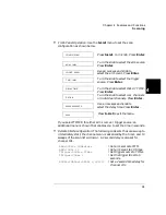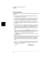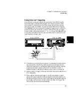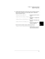
86
Chapter 4 Features and Functions
Scanning
4
The Scan Process
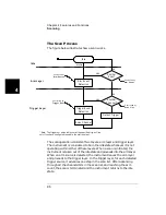
The figure below illustrates how a scan works.
The scan operation consists of two layers: arm layer and trigger layer.
The instrument is considered to be in the idle state whenever it is not
operating within either of these layers. When a scan is initiated, the
instrument is taken out of the idle state and proceeds into the arm layer.
When an arm source is detected, the instrument leaves the arm layer
and proceeds to the trigger layer. In the trigger layer, for each detected
trigger source, it advances one step in the scan list. After advancing
through all the channels/bits in the scan list, and reaching the arm
count, the scan is terminated and the instrument returns to the idle
state.
Idle
Trigger Event
Detection
Arm Event
Detection
Another
Scan?
Another
Channel?
yes
no
no
yes
Scan Channel
Output Trigger*
Idle
Trigger Layer
Arm Layer
C o n t r o l l e d b y
A r m S o u r c e
* Note: The trigger out pulse will occur at the specified trig-out line
only if you have configured to enable the slot to output.
C o n t r o l l e d b y
A r m C o u n t
C o n t r o l l e d b y
Trigger Source
C o n t r o l l e d b y
Scan List
Initialize
Summary of Contents for Agilent 3499A
Page 13: ...1 1 Quick Start ...
Page 27: ...2 2 Front Panel Operation ...
Page 55: ...3 3 System Overview ...
Page 77: ...4 4 Features and Functions ...
Page 113: ...5 5 Remote Interface Reference ...
Page 164: ...164 5 ...
Page 165: ...6 6 Error Messages ...
Page 173: ...7 7 Plug in Modules ...
Page 256: ...256 Chapter 7 Plug in Modules 44475A Breadboard Module 7 ...
Page 261: ...261 Chapter 7 Plug in Modules 44476B Microwave Switch Module 4 7 The 44476B is shown below ...
Page 286: ...286 Chapter 7 Plug in Modules Terminals and Connections Information 7 ...
Page 288: ...288 7 ...
Page 289: ...8 8 Application Programs ...
Page 299: ...9 9 Specifications ...
Page 343: ...343 Chapter 9 Specifications 44475A Breadboard Module 4 9 ...

