


66
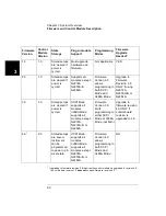
Chapter 3 System Overview
Plug-in Modules Overview
3
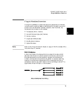
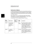
Matrix Modules
A matrix switch is the most versatile type of system switching. Any input
can be connected to any output, individually or in combination. This
helps minimize the need for complex wiring, and can simplify the DUT
interface. In addition, a matrix module can be used in conjunction with
other modules to provide a wide variety of switching combinations. A
matrix is arranged in rows and columns and a simple 4 x 4 matrix switch
is shown below.
Matrix Switching
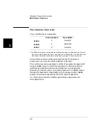
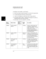
The table below lists the available matrix modules.
Model
Number
Module
Name
Mainframe
Slots
Required
Relay
Type
Description
N2262A
4 x 8 Matrix
Module
1
Latching
Each crosspoint or node of the 4 x 8
matrix module uses a DPST (Double-
pole Single-throw) relay to switch two
wires (Hi & Lo) for signals up to 200V,
1A.
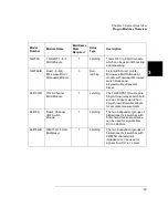
44473A
4 x 4 Matrix
Module
1
Latching
Each crosspoint or node of the 4 x 4
matrix module uses a DPST (Double-
pole Single-throw) relay to switch two
wires (Hi & Lo) for signals up to 250V,
2A.
Summary of Contents for Agilent 3499A
Page 13: ...1 1 Quick Start ...
Page 27: ...2 2 Front Panel Operation ...
Page 55: ...3 3 System Overview ...
Page 77: ...4 4 Features and Functions ...
Page 113: ...5 5 Remote Interface Reference ...
Page 164: ...164 5 ...
Page 165: ...6 6 Error Messages ...
Page 173: ...7 7 Plug in Modules ...
Page 256: ...256 Chapter 7 Plug in Modules 44475A Breadboard Module 7 ...
Page 261: ...261 Chapter 7 Plug in Modules 44476B Microwave Switch Module 4 7 The 44476B is shown below ...
Page 286: ...286 Chapter 7 Plug in Modules Terminals and Connections Information 7 ...
Page 288: ...288 7 ...
Page 289: ...8 8 Application Programs ...
Page 299: ...9 9 Specifications ...
Page 343: ...343 Chapter 9 Specifications 44475A Breadboard Module 4 9 ...