48
Chapter 2 Front-Panel Operation
To Configure the Remote Interface
2
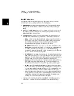
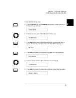
RS-232 Interface
RS-232 interface can be selected and its baud rate, parity, and flow
control mode can be configured from the front-panel.
•
Baud Rate: The baud rate can be set to one of the following: 2400,
4800, 9600, 19200, 38400, or 57600. The factory default setting is
9600.
•
Parity and Data Bits: The parity and data bits can be set to one of
the following: None, 8 bits; Even, 7 bits; or Odd, 7 bits. The factory
default setting is None, 8 bits.
•
Flow Control: The flow control can be set to one of the following:
None (factory default setting), XON/XOFF, DTR/DSR, RTS/CTS.
• None: In this mode, data is sent and received over the interface
without any flow control. When using this method, use a slower
baud rate (< 9600 baud) and avoid sending more than 128
characters without stopping or reading a response.
• XON/XOFF: This mode uses special characters embedded in the
data stream to control the flow. If the instrument is addressed to
send data, it continues sending data until the “XOFF” (13
h
)
character is received. When the “XON” character (11
h
) is received,
the instrument resumes sending data.
• DTR/DSR: In this mode, the instrument monitors the state of the
DSR (data set ready) line on the RS-232 connector. When the line
goes true, the instrument sends data over the interface. When the
line goes false, the instrument stops sending information
(typically within six characters). The instrument sets the DTR line
false when the input buffer is almost full (approximately 100
characters) and releases the line when space is available again.
• RTS/CTS: This mode operates the same as the DTR/DSR mode
but uses the RTS (request to send) and CTS (clear to send) lines on
the RS-232 connector instead. When the CTS line goes true, the
instrument sends data over the interface. When the line goes
false, the instrument stops sending information (typically within
six characters). The instrument sets the RTS line false when the
input buffer is almost full (approximately 100 characters) and
releases the line when space is available again.
• Changing the instrument system mode (SCPI or 3488) causes the
instrument to select the GPIB interface and its address setting.
Summary of Contents for Agilent 3499A
Page 13: ...1 1 Quick Start ...
Page 27: ...2 2 Front Panel Operation ...
Page 55: ...3 3 System Overview ...
Page 77: ...4 4 Features and Functions ...
Page 113: ...5 5 Remote Interface Reference ...
Page 164: ...164 5 ...
Page 165: ...6 6 Error Messages ...
Page 173: ...7 7 Plug in Modules ...
Page 256: ...256 Chapter 7 Plug in Modules 44475A Breadboard Module 7 ...
Page 261: ...261 Chapter 7 Plug in Modules 44476B Microwave Switch Module 4 7 The 44476B is shown below ...
Page 286: ...286 Chapter 7 Plug in Modules Terminals and Connections Information 7 ...
Page 288: ...288 7 ...
Page 289: ...8 8 Application Programs ...
Page 299: ...9 9 Specifications ...
Page 343: ...343 Chapter 9 Specifications 44475A Breadboard Module 4 9 ...


