351
4
Index
Digital I/O input/output
general rules 139
write to port 32
Digital I/O modules
general information 67
DIN Connector 7
Display 5
display message 110
DTR/DSR 48
dual 2-wire mode 178
E
EI/CC 93
enable/disable EI/CC 42
enable/disable trigger out pulse
42, 94
error messages 166
errors
execution 167
instrument 170
errors viewing/clearing 36, 108
errors, self-test 172
example program
VB.net 296
Visual BASIC 293
Visual C++ 291
example programs
Agilent BASIC 298
Visual BASIC 293
execution errors 167
external trigger 93
general rules 93
configuration 94
external trigger (3488A mode)
built-in TRIG IN/TRIG
OUT
specifications 302
configuration 42
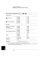
EI/CC specifications 341
external trigger (SCPI mode)
built-in TRIG IN/TRIG
OUT
specifications 302
configuration 42
EI/CC specifications 341
F
factory default 74
Features 2
FIFO 108
Filler Panels 7, 26
firmware
revision 52
revision 4.0 44
revision differences 106
flow control mode description
(DIO modules)
full handshake mode #5
102
read and write strobe mode
#4 101
read or write and strobe
mode #3 100
static mode #1 99
static mode #2 99
flow control mode description
(RS-232)
DTR/DSR 48
None 48
RTS/CTS 48
XON/XOFF 48
FP1 7, 26
FP2 7, 26
Front Panel 4
front-panel display
general description 5
on/off 110
text message 110
Front-Panel Operation 28
fu n ction m od e (N 2260A m od u le )
1-wire mode 178
2-wire mode 178
4-wire mode 178
dual 2-wire mode 178
G
GP modules
general information 64
GPIB (IEEE 488)
address selection 47
connector 6, 7
interface configuration 46
H
handshake mode description
(DIO modules)
default 99
full handshake mode #5
102
read and write strobe mode
#4 101
read or write and strobe
Mode #3 100
static mode #1 99
static mode #2 99
handshake mode description
(RS-232)
DTR/DSR 48
None 48
RTS/CTS 48
XON/XOFF 48
high-current relays (N2264A
module) 192
high-speed switching 84
I
idle state 86
IEEE 488.2 commands 161
INITiate 92, 138
Inoperative instrument 16
instrument
firmware revision 52
idle state 87
local/remote state 54
mounting onto rack 23
power on 29
power on failure 16
power on process 15
power-on state setting 44
recall state 107
serial number 53
state storage 106
store state 107
system mode selection 112
unpacking & inspection 15
viewing errors 36
instrument errors 170
Insulation Displacement
Connector 278
Summary of Contents for Agilent 3499A
Page 13: ...1 1 Quick Start ...
Page 27: ...2 2 Front Panel Operation ...
Page 55: ...3 3 System Overview ...
Page 77: ...4 4 Features and Functions ...
Page 113: ...5 5 Remote Interface Reference ...
Page 164: ...164 5 ...
Page 165: ...6 6 Error Messages ...
Page 173: ...7 7 Plug in Modules ...
Page 256: ...256 Chapter 7 Plug in Modules 44475A Breadboard Module 7 ...
Page 261: ...261 Chapter 7 Plug in Modules 44476B Microwave Switch Module 4 7 The 44476B is shown below ...
Page 286: ...286 Chapter 7 Plug in Modules Terminals and Connections Information 7 ...
Page 288: ...288 7 ...
Page 289: ...8 8 Application Programs ...
Page 299: ...9 9 Specifications ...
Page 343: ...343 Chapter 9 Specifications 44475A Breadboard Module 4 9 ...


