


30
Chapter 2 Front-Panel Operation
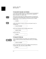
To Monitor a Channel or a Slot
2
.
Display
Description
The display for a multiplexer or a GP relay module. This
display indicates that the monitored module is in Slot 2 and
channels 10, 16, and 19 are closed.
The display for a matrix module. The top is the row
information, indicating that the relays on Row 3, Columns 1, 3,
6 and 7 of the module (in Slot 3) are closed. The lower display
is the column information, indicating that relays on column 3,
row 0 and 3 are closed.
The display for a digital I/O module. The first 2 digits on the left
(“00” in this case) represents the “L” 8-bit port address. Adding
one to this value, the “H” 8-bit port address is obtained. Data
with a trailing decimal point indicates that the last operation on
that port was a WRITE, data without a trailing decimal point
indicates that the last operation on that port was a READ. This
display shows that the data last read from Port 401 is 255 and
the data last written to Port 400 is 254.
The top display is for the built-in digital I/O Port 090 (control
module) and the data from the last operation.
The lower display indicates that data last written to the bit
channel 091 is 0.
For a multifunction module, the first function on the module is
displayed, then the next. This display is an example of a
multifunction module with matrix and DIO functions (in slot 5).
1:0,,,,,,6,,,9,
2
ROW 3:,1,,3,,,6,7
3
0;,,3,COL 3,
3
00:H255 L254.
4
DIO 12
090
DOUT 0
091
ROW 0:,1,,3,
5
00:H255 L254.
5
Summary of Contents for Agilent 3499A
Page 13: ...1 1 Quick Start ...
Page 27: ...2 2 Front Panel Operation ...
Page 55: ...3 3 System Overview ...
Page 77: ...4 4 Features and Functions ...
Page 113: ...5 5 Remote Interface Reference ...
Page 164: ...164 5 ...
Page 165: ...6 6 Error Messages ...
Page 173: ...7 7 Plug in Modules ...
Page 256: ...256 Chapter 7 Plug in Modules 44475A Breadboard Module 7 ...
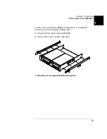
Page 261: ...261 Chapter 7 Plug in Modules 44476B Microwave Switch Module 4 7 The 44476B is shown below ...
Page 286: ...286 Chapter 7 Plug in Modules Terminals and Connections Information 7 ...
Page 288: ...288 7 ...
Page 289: ...8 8 Application Programs ...
Page 299: ...9 9 Specifications ...
Page 343: ...343 Chapter 9 Specifications 44475A Breadboard Module 4 9 ...