


29
Chapter 2 Front-Panel Operation
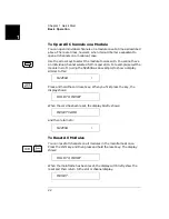
To Power On the Instrument
4
2
To Power On the Instrument
To power on the instrument, press the power switch on the front panel.
If the instrument is powered up for the first time, the instrument will
use the factory default settings as shown on page 74. Otherwise, the
instrument will power on to the state specified. Refer to "To Configure
the Power-on State", on page 44 for more details.
To Monitor a Channel or a Slot
You can continuously monitor the current status of a particular
switching channel, a digital I/O port, or an entire plug-in module.
Monitoring from the front panel is especially useful when developing and
debugging remote interface commands.
1. Press the monitor key, the MON annunciator lights up to indicate the
instrument is in the monitoring state.
2. Select the slot or the channel/port to be monitored. The displayed
information depends on the selected module type. Typical displays
are shown in the table on page 81.
3. If only part of the channel status on the module can be displayed at
one time, press Enter to display the next part.
For multiplexer modules and GP Relay modules, 10 channels can be
displayed at one time; for matrix modules, one Row or one Column
can be displayed at one time; for digital I/O modules, two 8-bit ports
can be displayed at one time. For multifunction modules, the first
function on the module is displayed, then the next.
4. Press the monitor key again to end monitoring (the MON
annunciator turns off).
Note
The built-in digital I/O bits/port (on the controller module) can be
monitored either individually as bit channels (numbered 091 through
094) or as a 4-bit port (numbered 090). However, the individual bit
channels on a digital I/O or multifunction module (with a DIO function)
cannot be monitored.
Summary of Contents for Agilent 3499A
Page 13: ...1 1 Quick Start ...
Page 27: ...2 2 Front Panel Operation ...
Page 55: ...3 3 System Overview ...
Page 77: ...4 4 Features and Functions ...
Page 113: ...5 5 Remote Interface Reference ...
Page 164: ...164 5 ...
Page 165: ...6 6 Error Messages ...
Page 173: ...7 7 Plug in Modules ...
Page 256: ...256 Chapter 7 Plug in Modules 44475A Breadboard Module 7 ...
Page 261: ...261 Chapter 7 Plug in Modules 44476B Microwave Switch Module 4 7 The 44476B is shown below ...
Page 286: ...286 Chapter 7 Plug in Modules Terminals and Connections Information 7 ...
Page 288: ...288 7 ...
Page 289: ...8 8 Application Programs ...
Page 299: ...9 9 Specifications ...
Page 343: ...343 Chapter 9 Specifications 44475A Breadboard Module 4 9 ...