283
Chapter 7 Plug-in Modules
Terminals and Connections Information
4
7
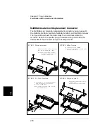
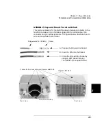
N2320A Crimp and Insert Terminal Block
This terminal block is for the N2270A plug-in module only. Refer to the
N2270A module wiring information (page 213) for details about the
connector and pin-out assignments. The figures below illustrate how to
wire and assemble this terminal.
Stripped wire (14-18 AWG)
Socket
A. Prepare the Wire and the Socket.
B. Insert the Wire into the Socket.
C. Crimp the Wire with the Socket by
using an AMP Hand Crimping
Tool (90067-5) or equivalent tool.
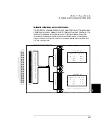
m etal strain relief clam p
R elease the fo ur screws a nd uncover the upper metal shield
R e a r v ie w
F ro n t vie w
Upper m etal shield
Summary of Contents for Agilent 3499A
Page 13: ...1 1 Quick Start ...
Page 27: ...2 2 Front Panel Operation ...
Page 55: ...3 3 System Overview ...
Page 77: ...4 4 Features and Functions ...
Page 113: ...5 5 Remote Interface Reference ...
Page 164: ...164 5 ...
Page 165: ...6 6 Error Messages ...
Page 173: ...7 7 Plug in Modules ...
Page 256: ...256 Chapter 7 Plug in Modules 44475A Breadboard Module 7 ...
Page 261: ...261 Chapter 7 Plug in Modules 44476B Microwave Switch Module 4 7 The 44476B is shown below ...
Page 286: ...286 Chapter 7 Plug in Modules Terminals and Connections Information 7 ...
Page 288: ...288 7 ...
Page 289: ...8 8 Application Programs ...
Page 299: ...9 9 Specifications ...
Page 343: ...343 Chapter 9 Specifications 44475A Breadboard Module 4 9 ...


