


253
Chapter 7 Plug-in Modules
44475A Breadboard Module
4
7
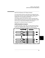
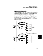
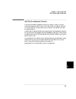
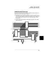
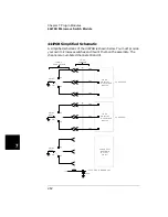
44475A Simplified Schematic
A simplified schematic of the breadboard interface is shown below. The
44475A is divided into two areas. They are:
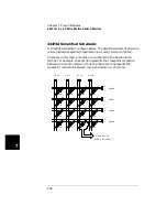
1. Breadboarding Grid consisting of holes on 0.10 inch centers. There is
0.030 inch spacing between foil pads. Bus traces for power supply and
ground, and provisions for the screw terminal block edge connector
are provided.
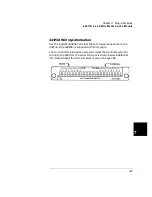
2. Built-in design for providing an 8-bit digital input port and an 8-bit
digital output port.
3-STATE
D0
D1
D2
D3
D4
D5
D6
D7
+5
R/W
CS
A1
+5
B-GND
0.01
1.0
+5
DI0
DI1
DI2
DI3
DI4
DI5
DI6
DI7
DO0
DO1
DO2
DO3
DO4
DO5
DO6
DO7
LS374
LS138
LS244
LS157
6
1
2
3
4
5
8
15
14
3
5
7
9
12
14
16
18
1
19
2
4
6
8
11
13
15
17
18
17
14
13
8
7
4
3
1
11
19
16
15
12
9
6
5
2
12
9
4
1
14
11
5
2
15
13
3
6
10
7
Summary of Contents for Agilent 3499A
Page 13: ...1 1 Quick Start ...
Page 27: ...2 2 Front Panel Operation ...
Page 55: ...3 3 System Overview ...
Page 77: ...4 4 Features and Functions ...
Page 113: ...5 5 Remote Interface Reference ...
Page 164: ...164 5 ...
Page 165: ...6 6 Error Messages ...
Page 173: ...7 7 Plug in Modules ...
Page 256: ...256 Chapter 7 Plug in Modules 44475A Breadboard Module 7 ...
Page 261: ...261 Chapter 7 Plug in Modules 44476B Microwave Switch Module 4 7 The 44476B is shown below ...
Page 286: ...286 Chapter 7 Plug in Modules Terminals and Connections Information 7 ...
Page 288: ...288 7 ...
Page 289: ...8 8 Application Programs ...
Page 299: ...9 9 Specifications ...
Page 343: ...343 Chapter 9 Specifications 44475A Breadboard Module 4 9 ...