


246
Chapter 7 Plug-in Modules
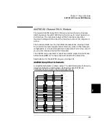
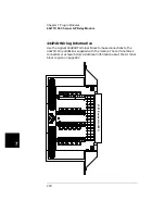
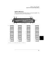
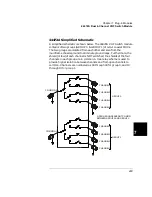
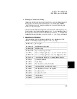
44473A 4 x 4 2-Wire Matrix Switch Module
7
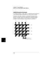
44473A Simplified Schematic
A simplified schematic is shown below. The 44473A consists of 16 2-wire
relays (nodes/crosspoints) organized in a 4-row by 4-column matrix.
Channels in this matrix module are numbered in the Row-Column
format. For example, channel 32 represents the crosspoint connection
between row 3 and column 2; while the channel 23 represents the
crosspoint connection between row 2 and column 3, and so on.
ROW0
COL0
ROW1
COL1
ROW2
COL2
ROW3
COL3
H L
H
L
CHANNEL 32
(ROW 3, COLUMN 2)
H L
H L
H L
H
L
H
L
H
L
00
01
02
03
10
11
12
13
20
21
22
23
30
31
33
Summary of Contents for Agilent 3499A
Page 13: ...1 1 Quick Start ...
Page 27: ...2 2 Front Panel Operation ...
Page 55: ...3 3 System Overview ...
Page 77: ...4 4 Features and Functions ...
Page 113: ...5 5 Remote Interface Reference ...
Page 164: ...164 5 ...
Page 165: ...6 6 Error Messages ...
Page 173: ...7 7 Plug in Modules ...
Page 256: ...256 Chapter 7 Plug in Modules 44475A Breadboard Module 7 ...
Page 261: ...261 Chapter 7 Plug in Modules 44476B Microwave Switch Module 4 7 The 44476B is shown below ...
Page 286: ...286 Chapter 7 Plug in Modules Terminals and Connections Information 7 ...
Page 288: ...288 7 ...
Page 289: ...8 8 Application Programs ...
Page 299: ...9 9 Specifications ...
Page 343: ...343 Chapter 9 Specifications 44475A Breadboard Module 4 9 ...