211
Chapter 7 Plug-in Modules
N2268A 50
Ω
3.5 GHz Dual 1-to-4 MUX Module
4
7
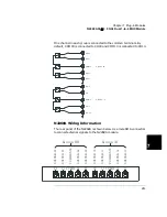
One channel in each group is connected to the common terminals. By
default, COM00 is connected to CH00 and COM10 is connected to CH10.
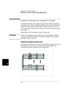
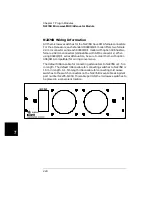
N2268A Wiring Information
The rear panel of the N2268A is shown below. Use male SMA connectors
to connect external signals to the N2268A module.
CH00
CH01
COM00
CH03
CH02
CH10
CH11
COM10
CH12
CH130
GROUP 00
GROUP 10
C
HA
NNE
L
00
C
HA
NNE
L
03
C
HA
NNE
L
02
C
O
MM
O
N
00
C
HA
NNE
L
01
C
HA
NNE
L
10
C
HA
NNE
L
13
C
HA
NNE
L
12
CO
M
M
O
N
10
C
HA
NNE
L
11
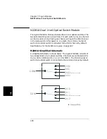
Group 00
Group 10
00
01 COM00 02
03
10
11 COM10 12
13
Summary of Contents for Agilent 3499A
Page 13: ...1 1 Quick Start ...
Page 27: ...2 2 Front Panel Operation ...
Page 55: ...3 3 System Overview ...
Page 77: ...4 4 Features and Functions ...
Page 113: ...5 5 Remote Interface Reference ...
Page 164: ...164 5 ...
Page 165: ...6 6 Error Messages ...
Page 173: ...7 7 Plug in Modules ...
Page 256: ...256 Chapter 7 Plug in Modules 44475A Breadboard Module 7 ...
Page 261: ...261 Chapter 7 Plug in Modules 44476B Microwave Switch Module 4 7 The 44476B is shown below ...
Page 286: ...286 Chapter 7 Plug in Modules Terminals and Connections Information 7 ...
Page 288: ...288 7 ...
Page 289: ...8 8 Application Programs ...
Page 299: ...9 9 Specifications ...
Page 343: ...343 Chapter 9 Specifications 44475A Breadboard Module 4 9 ...


