


201
Chapter 7 Plug-in Modules
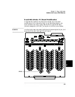
N2266A 40-Channel MUX Module
4
7
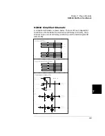
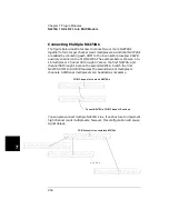
N2266A Simplified Schematic
The 40 2-wire channel relays (CH00-CH39) are divided into two banks:
BANK 0 and BANK 1. Each bank consists of 20 2-wire switching
channels and a common bus (COM0 & COM1). There is also a single-
ended common terminal (SE-COM) used when the multiplexer is
configured to 80-channel 1-wire mode. The two tree relays, T98 and T99,
are used to configure the N2260A.
L
H
L
H CH00
L
H
L
H CH09
L
H
L
H CH19
SE-COM
L
H
L
H CH10
CH00
CH09
CH19
CH10
L
H
L
H CH29
L
H
L
H CH20
L
H
L
H CH39
L
H
L
H CH30
CH39
CH30
L
H
COMMON BUS
COM0
CH20
L
H
COMMON BUS
COM1
CH29
BANK 0
BANK 1
T98
T99
N2266A
MUX Module
Terminal Block
Summary of Contents for Agilent 3499A
Page 13: ...1 1 Quick Start ...
Page 27: ...2 2 Front Panel Operation ...
Page 55: ...3 3 System Overview ...
Page 77: ...4 4 Features and Functions ...
Page 113: ...5 5 Remote Interface Reference ...
Page 164: ...164 5 ...
Page 165: ...6 6 Error Messages ...
Page 173: ...7 7 Plug in Modules ...
Page 256: ...256 Chapter 7 Plug in Modules 44475A Breadboard Module 7 ...
Page 261: ...261 Chapter 7 Plug in Modules 44476B Microwave Switch Module 4 7 The 44476B is shown below ...
Page 286: ...286 Chapter 7 Plug in Modules Terminals and Connections Information 7 ...
Page 288: ...288 7 ...
Page 289: ...8 8 Application Programs ...
Page 299: ...9 9 Specifications ...
Page 343: ...343 Chapter 9 Specifications 44475A Breadboard Module 4 9 ...