


196
Chapter 7 Plug-in Modules
N2265A Multifunction Module
7
N2265A Multifunction Module
The Agilent N2265A is a multifunction module which consists of:
•
A 4 x 4 2-wire Matrix module (16 latching relays) and;
•
A 16-bit digital I/O module.
The parallel switching feature makes the matrix portion of this module
well suited for high-speed switching applications. Up to eight 2-wire
node/crosspoint relays in the same row can be closed all at once (parallel
switching). Additional information about parallel switching is given on
page 84.
Five handshaking modes are available for the digital I/O function. The
handshaking modes are described beginning on page 98. Handshaking
uses up to three control lines:
•
Peripheral Control (PCTL)
•
I/O direction (I/O)
•
Peripheral Flag (PFLG)
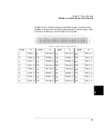
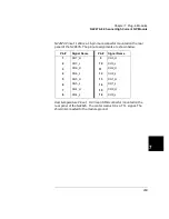
Port and bit numbering is show in the table below. Note that the ports
are numbered differently if you are using the 3488 System mode.
Specifications for the N2265A are shown on page 313.
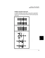
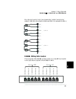
N2265A Simplified Schematic
A simplified schematic of the N2265A is shown on the next page. The
N2265A is separated into two sections: the 4 x 4 2-wire matrix and the
16-bit digital I/O. A channel on the N2265A refers to an individual
crosspoint on the matrix, or an individual bit on the 16-bit digital I/O.
Operating Mode
16-Bit Port #
8-Bit Port #
Bit #
SCPI mode
PORT 40
PORT 40
Bits 40-47
PORT 41
Bits 48-55
3488A Mode
PORT 42
PORT 40
Bits 40-47
PORT 41
Bits 48-55
Summary of Contents for Agilent 3499A
Page 13: ...1 1 Quick Start ...
Page 27: ...2 2 Front Panel Operation ...
Page 55: ...3 3 System Overview ...
Page 77: ...4 4 Features and Functions ...
Page 113: ...5 5 Remote Interface Reference ...
Page 164: ...164 5 ...
Page 165: ...6 6 Error Messages ...
Page 173: ...7 7 Plug in Modules ...
Page 256: ...256 Chapter 7 Plug in Modules 44475A Breadboard Module 7 ...
Page 261: ...261 Chapter 7 Plug in Modules 44476B Microwave Switch Module 4 7 The 44476B is shown below ...
Page 286: ...286 Chapter 7 Plug in Modules Terminals and Connections Information 7 ...
Page 288: ...288 7 ...
Page 289: ...8 8 Application Programs ...
Page 299: ...9 9 Specifications ...
Page 343: ...343 Chapter 9 Specifications 44475A Breadboard Module 4 9 ...