


186
Chapter 7 Plug-in Modules
N2262A 4 x 8 2-Wire Matrix Switch Module
7
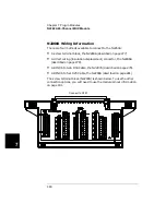
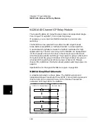
N2262A Wiring Information
There are three methods available to connect to the N2262A:
•
A screw terminal block, the N2292A (described on page 277).
•
A direct wiring (insulation displacement) connector, the N2296A
(described on page 278).
•
A DIN96 to twin D25 Cable, the N2298A (described on page 280).
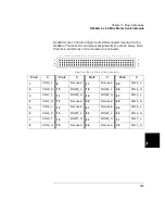
The screw terminal block (N2292A) is shown below. To use the other
connection options, you will need to use the pinout information on page
187.
(CON NECT T O P300)
Summary of Contents for Agilent 3499A
Page 13: ...1 1 Quick Start ...
Page 27: ...2 2 Front Panel Operation ...
Page 55: ...3 3 System Overview ...
Page 77: ...4 4 Features and Functions ...
Page 113: ...5 5 Remote Interface Reference ...
Page 164: ...164 5 ...
Page 165: ...6 6 Error Messages ...
Page 173: ...7 7 Plug in Modules ...
Page 256: ...256 Chapter 7 Plug in Modules 44475A Breadboard Module 7 ...
Page 261: ...261 Chapter 7 Plug in Modules 44476B Microwave Switch Module 4 7 The 44476B is shown below ...
Page 286: ...286 Chapter 7 Plug in Modules Terminals and Connections Information 7 ...
Page 288: ...288 7 ...
Page 289: ...8 8 Application Programs ...
Page 299: ...9 9 Specifications ...
Page 343: ...343 Chapter 9 Specifications 44475A Breadboard Module 4 9 ...