


185
Chapter 7 Plug-in Modules
N2262A 4 x 8 2-Wire Matrix Switch Module
4
7
N2262A 4 x 8 2-Wire Matrix Switch Module
The Agilent N2262A 4 x 8 Matrix module contains 32 2-wire nodes
(crosspoints) organized in a 4-row by 8-column configuration. Each node
in the matrix contains a 2-wire latching relay for switching both Hi (H)
and Lo (L) terminals of a signal line. Multiple switches can be closed,
allowing any combination of row-to-column connections.
The parallel switching feature makes it well suited for high speed
switching applications. Up to 8 2-wire node/crosspoint relays in the same
row can be closed all at once (parallel switching).
The N2262A provides a convenient way to connect multiple test
instruments to multiple test points on a device or to multiple devices.
Multiple N2262A modules can be connected together, or used in
conjunction with other modules such as the N2260A 40-Channel MUX to
provide a wide variety of switching combinations.
Specifications for the Agilent N2262A are given on page 307.
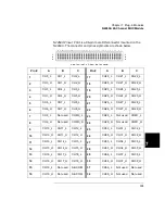
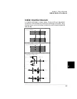
N2262A Simplified Schematic
A simplified schematic is shown below. The N2262A contains
32 2-wire crosspoints organized in a 4-row by 8-column configuration.
Each crosspoint relay has a unique two digit channel number
mn,
where
m
= row number (0-3) and
n
= column number (0-7).
ROW0
ROW1
ROW2
ROW3
COL0
H L
COL1
H L
COL7
H L
H
L
H
L
H
L
H
L
CHANNEL 31
(ROW 3, COLUMN 1)
00
01
07
10
11
20
21
17
27
30
31
37
Channel 31 represents the relay
at the crosspoint of Row 3
(ROW3) and Column 1 (COL1).
Summary of Contents for Agilent 3499A
Page 13: ...1 1 Quick Start ...
Page 27: ...2 2 Front Panel Operation ...
Page 55: ...3 3 System Overview ...
Page 77: ...4 4 Features and Functions ...
Page 113: ...5 5 Remote Interface Reference ...
Page 164: ...164 5 ...
Page 165: ...6 6 Error Messages ...
Page 173: ...7 7 Plug in Modules ...
Page 256: ...256 Chapter 7 Plug in Modules 44475A Breadboard Module 7 ...
Page 261: ...261 Chapter 7 Plug in Modules 44476B Microwave Switch Module 4 7 The 44476B is shown below ...
Page 286: ...286 Chapter 7 Plug in Modules Terminals and Connections Information 7 ...
Page 288: ...288 7 ...
Page 289: ...8 8 Application Programs ...
Page 299: ...9 9 Specifications ...
Page 343: ...343 Chapter 9 Specifications 44475A Breadboard Module 4 9 ...