105
Chapter 4 Features and Functions
Digital I/O Operation
4
4
Digital Output Operation
•
From the front-panel, you can write data to the built-in digital I/O
bits/port (numbered 090 through 094) or any one of the 8-bit ports on
a digital I/O module or multifunction module.
•
From the remote interface, you can write data to individual bit
channels and 8-, 16-, or 32-bit ports on a digital I/O module or
multifunction module, as well as to the built-in digital I/O bits/port
(numbered 090 through 094).
•
Instrument reset will set all digital I/O ports in the instrument as
input ports. Pressing Card Reset or issuing a
SYST:CPON
command
will set all ports on the specified module as input ports (ports on other
modules are not affected).
•
Front-Panel Operation: Select an 8-bit port, press Write, the data
from the last operation (read or write) will be displayed. Edit the data
to the desired value and press Enter to write the data to the port. To
cancel the write operation, press Write again instead of Enter. You
can edit the data in either binary or decimal form (see page 34).
•
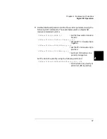
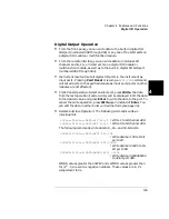
Remote Interface Operation: The following commands write an
individual bit.
SOURce:DIGital:DATA:BIT 409,1
! Write 1 to bit channel 409.
SOURce:DIGital:DATA:BIT 409,0
! Write 0 to bit channel 409.
The following commands write date to 8-, 16-, and 32-bit ports.
SOURCE:DIGital:DATA:BYTE 400,128
! Write decimal 128 to 8-bit
port 400.
SOURCE:DIGital:DATA:WORD 400,21845
! Write decimal 21845 to 16-
bit port 400.
SOURCE:DIGital:DATA:LWORD 400, -2114
! Write decimal 4294965182
to 32-bit port 400.
WORD values greater then 32767 and LWORD values greater then
for
(2
31
-1)
are sent as negative numbers. These values are in 2’s
complement form.
Summary of Contents for Agilent 3499A
Page 13: ...1 1 Quick Start ...
Page 27: ...2 2 Front Panel Operation ...
Page 55: ...3 3 System Overview ...
Page 77: ...4 4 Features and Functions ...
Page 113: ...5 5 Remote Interface Reference ...
Page 164: ...164 5 ...
Page 165: ...6 6 Error Messages ...
Page 173: ...7 7 Plug in Modules ...
Page 256: ...256 Chapter 7 Plug in Modules 44475A Breadboard Module 7 ...
Page 261: ...261 Chapter 7 Plug in Modules 44476B Microwave Switch Module 4 7 The 44476B is shown below ...
Page 286: ...286 Chapter 7 Plug in Modules Terminals and Connections Information 7 ...
Page 288: ...288 7 ...
Page 289: ...8 8 Application Programs ...
Page 299: ...9 9 Specifications ...
Page 343: ...343 Chapter 9 Specifications 44475A Breadboard Module 4 9 ...

