103
Chapter 4 Features and Functions
Digital I/O Operation
4
4
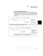
DATA LINES
I/O DIRECTION
R e a d O pe ratio n
DATA VALID
LATCHED
PFLG LINE
PCTL LINE
t1
100
µ
s
t2
45
µ
s
t3
50
µ
s
t4
40
µ
s
t5
35
µ
s
t1 = T im e fro m ou tp u t
d is a b le to I/O lin e
h ig h (1 0 0
µ
s m in im u m )
t2 = T im e fro m I/O lin e
h igh to ch eck for
P F L G lo w
t3 = T im e fro m P F L G low
to ch eck fo r P C T L
lo w (5 0
µ
s m in im u m )
t4 = T im e fro m P C T L low
to ch eck P F L G
h ig h (4 0
µ
s m in im u m )
t5 = T im e fro m P F L G
h ig h t o P C T L h igh
a n d d a ta la tch ed
(3 5
µ
s m in im u m )
(4 5
µ
s m in im u m )
As with the Write operation, the 3499A/B/C begins by testing PFLG for a
low state, indicating that the data is valid. When PFLG is low, the
3499A/B/C sets PCTL low and waits for PFLG to go high. The 3499A/B/C
will set PCTL high to indicate that it has completed the data read operation.
Data on the data bus must remain valid until after the 3499A/B/C sets
PCTL high.
Summary of Contents for Agilent 3499A
Page 13: ...1 1 Quick Start ...
Page 27: ...2 2 Front Panel Operation ...
Page 55: ...3 3 System Overview ...
Page 77: ...4 4 Features and Functions ...
Page 113: ...5 5 Remote Interface Reference ...
Page 164: ...164 5 ...
Page 165: ...6 6 Error Messages ...
Page 173: ...7 7 Plug in Modules ...
Page 256: ...256 Chapter 7 Plug in Modules 44475A Breadboard Module 7 ...
Page 261: ...261 Chapter 7 Plug in Modules 44476B Microwave Switch Module 4 7 The 44476B is shown below ...
Page 286: ...286 Chapter 7 Plug in Modules Terminals and Connections Information 7 ...
Page 288: ...288 7 ...
Page 289: ...8 8 Application Programs ...
Page 299: ...9 9 Specifications ...
Page 343: ...343 Chapter 9 Specifications 44475A Breadboard Module 4 9 ...


