


Chapter 7
7-99
Programming Examples
List-Frequency and Limit-Test Table Examples
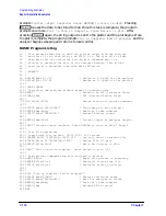
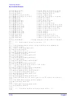
Example 6E: Performing PASS/FAIL Tests While Tuning
The purpose of this example is to demonstrate the use of the limit/search-fail bits in
event-status register B, to determine whether a device passes the specified limits. Limits
can be entered manually, or using Example 6D.
The limit/search-fail bits are set and latched when limit testing or a marker search fails.
There are four bits, one for each channel for both limit testing and marker search. See
and
for additional information. Their purpose
is to allow the computer to determine whether the test/search executed was successful.
They are used in the following sequence:
1. Clear event-status register B.
2. Trigger the limit test or marker search.
3. Check the appropriate fail bit.
When using limit testing, the best way to trigger the limit test is to trigger a single sweep.
By the time the single sweep command (
SING
) finishes, limit testing will have occurred.
NOTE
If the device is tuned during the sweep, it may be tuned into and then out of
limit, causing a limit test to qualify as “passed” when the device is not in fact
within the specified limits.
When using marker searches (max, min, target, and widths), outputting marker or
bandwidth values automatically triggers any related searches. Therefore, all that is
required is to check the fail bit after reading the data.
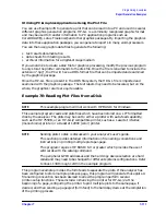
In this example, several consecutive sweeps must qualify as “passing” in order to ensure
that the limit-test pass was not extraneous due to the device settling or operator tuning
during the sweep. Upon running the program, the number of “passed” sweeps for
qualification is entered. For very slow sweeps, a small number of sweeps such as two are
appropriate. For relatively fast sweeps, where the device requires time to settle after
tuning, as many as six or more sweeps may be more appropriate.
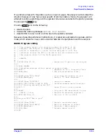
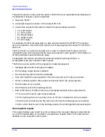
The following is an outline of the program's processing sequence:
• An I/O path is assigned for the analyzer.
• The system is initialized.
• The pass counter is initialized on entry.
• The analyzer takes a sweep.
• The event-status register B byte is output and the channel-1 limit is tested.
• If the device fails the first sweep, the operator is prompted to ensure it is tuned
correctly and the device is measured again.
• If the device passes the first sweep, the operator is prompted not to touch the device as
testing continues.
• If the device passes the required number of sweeps, the operator is prompted that the
device has passed and to connect the next device for testing.
• The program initializes the pass counter and begins to measure the new device.
Summary of Contents for 8719ES
Page 15: ...1 1 1 Alphabetical Command Reference ...
Page 293: ...2 1 2 Introduction to Instrument Control ...
Page 310: ...3 1 3 GPIB Programming ...
Page 334: ...4 1 4 Reading Analyzer Data ...
Page 343: ...5 1 5 Data Processing Chain ...
Page 350: ...6 1 6 Error Reporting ...
Page 364: ...7 1 7 Programming Examples ...
Page 502: ...A 1 A Preset Conditions ...
Page 517: ...B 1 B Command Listings ...


