


Agilent 86038B Photonic Dispersion and Loss Analyzer, Second Edition
29
• If the instrument includes more than one TLS, but will use
only one 8164B, choose the TLS to be installed in the
8164B for the first operation.
3 Place the analyzer unit on top of the TLS mainframe.
• If more than one 8164B is included, identify the "master"
mainframe for this position. This 8164B will be used for
installing switch and power meter options. The optional
additional mainframes can be installed under or beside
the master mainframe.
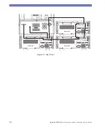
4 On the rear panel, connect the cables as shown in Figure 2a.
• If more than one 8164B, the additional trigger cables
should be attached in daisy-chain configuration as shown
in Figure 2b. Each mainframe should also be connected to
the GPIB, as shown. Note that with this trigger
configuration, all 8164B units should be switched on for
correct trigger behavior.
5
Connect the mouse and keyboard via USB ports at the back
and front of the analyzer unit.
6 On the front panel, connect the 40 cm black protected
patchcord (labeled "TLS Fiber") between TLS Output 2 and
the TLS Input of the analyzer as shown in Figure 1. This
patchcord is polarization maintaining fiber (PMF) and
should not be interchanged with standard fibers. The
connectors make angled contact.
• Standard operation is provided by using the high-power
Output 2 of the TLS, which includes variable attenuator
functionality. However for special applications, the Output
1 can be used at any time to obtain a signal with very low
spontaneous emission (broadband background light).
• If a special PMF-switch for multi-TLS automation is
included, this module should be inserted in Slot 4 of the
master 8164B. Then the fiber from the TLS in this
mainframe should be connected to Port 1 of the PMF-
switch and the additional "TLS Fiber" included with the
switch should be connected between the Port A (common)
of the switch and the TLS Input of the analyzer. Additional
tunable lasers can be similarly connected with PMF
patchcords to the other ports of the PMF-switch.
The network analyzer and optical test set are assembled as one
analyzer unit. The combined weight is 38 kg (84 lbs). The lifting of
this instrument requires two persons using proper lifting
techniques.
C A U T I O N
Summary of Contents for 86038B
Page 1: ...Agilent 86038B Photonic Dispersion and Loss Analyzer User s Guide ...
Page 4: ...4 ...
Page 20: ...20 Agilent 86038B Photonic Dispersion and Loss Analyzer Second Edition ...
Page 34: ...34 Agilent 86038B Photonic Dispersion and Loss Analyzer Second Edition Figure 2 b Rear Panel ...
Page 78: ...78 Agilent 86038B Photonic Dispersion and Loss Analyzer Second Edition ...
Page 92: ...92 Agilent 86038B Photonic Dispersion and Loss Analyzer Second Edition ...
Page 202: ...202 Agilent 86038B Photonic Dispersion and Loss Analyzer Second Edition End Sub ...
Page 348: ...348 Agilent 86038B Photonic Dispersion and Loss Analyzer Second Edition ...
Page 349: ......


