


4-4
Chapter 4
Operation
Operator’s Check
Operator’s Check
The operator’s check is designed to be a simple functional test for the probe. If the probe fails the
operator’s check, or if you need to verify that the probe meets its warranted specifications, you will need
to do the performance tests as described in
Chapter 5 , “Performance Tests.”
The operator’s check can be performed with either a network analyzer or a spectrum analyzer. Use one of
the following two procedures to perform the operator’s check.
Operator’s check Using a Network Analyzer
Required Equipment
Procedure
NOTE
If you are not familiar with network analyzer operation, refer to
for basic information about performing the analyzer operations
used in this procedure.
1. Preset the analyzer using the
hardkey.
2. Configure the analyzer to measure transmission.
3. Set the output power level of the analyzer to 0 dBm.
4. Set the frequency sweep range on the analyzer from 300 kHz to 3 GHz.
5. Connect a type-N cable (a through cable) between the output and the input ports on the analyzer.
6. Perform a response calibration on the analyzer. The trace on the analyzer should now be flat at 0 dB.
7. Remove the through cable. Connect the probe adapter to the output port of the analyzer. Connect the
output of the probe to the input port of the analyzer. Connect the probe power cable to a power
source.
8. Plug the probe tip into the adapter.
9. The trace of the analyzer should be within
5 dB of 0 dB.
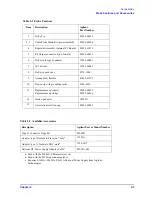
Item
Part Number
Network Analyzer
Any compatible with
type-N connectors
Type-N Cable
50
male connectors
Probe Adapter
11880-60001
PRESET
Summary of Contents for 85024A
Page 4: ...iv ...
Page 7: ...1 1 1 General Information ...
Page 13: ...2 1 2 Accessories ...
Page 19: ...3 1 3 Installation ...
Page 24: ...3 6 Chapter3 Installation Returning the Product for Service ...
Page 25: ...4 1 4 Operation ...
Page 30: ...4 6 Chapter4 Operation Operator s Check ...
Page 31: ...5 1 5 Performance Tests ...
Page 40: ...5 10 Chapter5 Performance Tests Average Noise Level ...
Page 41: ...6 1 6 Replaceable Parts ...
Page 46: ...6 6 Chapter6 Replaceable Parts Parts Lists ...
Page 47: ...7 1 7 Service ...
Page 60: ...7 14 Chapter7 Service Replacement Procedure Figure 7 11 Regulator Parts and Wiring ...
Page 64: ...7 18 Chapter7 Service Connector Inspection and Cleaning ...


