


5-17
Servicing
Troubleshooting
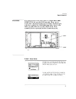
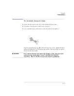
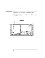
To check the A2A2 Laser Modulation Board Assembly
1
Check the +5V supply by probing the center pin of J11. The modulation input
cable from the rear panel connects to this jack.
2
Check the –15V supply by probing any of the three resistors that are located
next to J2. These resistors are loaded in a straight line and have the label “1471”
printed on them.
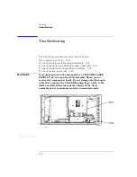
3
Locate the large 3W black resistor on the assembly that is closest to the pump
laser.
4
Measure the voltage on the end of the resistor that is furthest from the pump
laser. The voltage should measure approximately –1V to –2V.
5
The pump laser is being driven by the current source and should be turned on.
6
Press the front-panel
ACTIVE
key so that the front-panel
ACTIVE
light is turned
off. The voltage measured at the 3W resistor should now be approximately
+0.7V.
The pump laser is turned off.
7
If the voltage measured across the resistor is incorrect, return the instrument
to Agilent Technologies for servicing.
Summary of Contents for 83437A
Page 1: ...Agilent 83438A Erbium ASE Source User s Guide ...
Page 5: ...v The Agilent 83438A At a Glance Rear view of instrument ...
Page 8: ......
Page 10: ......
Page 24: ...2 4 Making Measurements Performing Stimulus Response Measurements ...
Page 41: ...3 Specifications 3 3 Regulatory Information 3 6 Specifications and Regulatory Information ...
Page 48: ......
Page 54: ......
Page 61: ...5 7 Servicing General Information ...
Page 63: ...5 9 Servicing General Information ...
Page 79: ...5 25 Servicing Adjustment Procedure ...
Page 85: ...5 31 Servicing Replacing Instrument Assemblies Location of resistors R2 R8 and R9 ...
Page 92: ...5 38 Servicing Replaceable Parts ...
Page 94: ...5 40 Servicing Replaceable Parts ...
Page 96: ...5 42 Servicing Replaceable Parts ...
Page 98: ...5 44 Servicing Replaceable Parts ...
Page 100: ...5 46 Servicing Replaceable Parts ...
Page 106: ......