background image

ParBERT Components Overview 

2 Introduction 


Agilent 81250 ParBERT Installation Guide, May 2004 

2-3 

If you order ParBERT with a controller PC, all required hardware and 
software is factory-installed, and the tester is ready for use. If you have 
ordered ParBERT without a controller PC, you have to install the 
interface and software on your PC. 

Older ParBERT versions were shipped with an 

embedded controller

. This 

is a special VXI module that communicates directly with the VXI bus. It 
occupies the two leftmost slots of the first mainframe and does not use 
the IEEE 1394 PC link to VXI.  

If you wish to add mainframes to a ParBERT with embedded controller, 
please refer to 

“Expanding Systems with Embedded Controller” on  

page 7-23

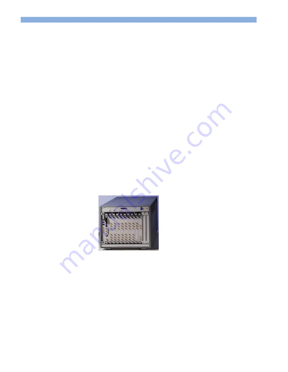
The ParBERT Mainframes 

ParBERT mainframe is the E8403A or E8404A VXI mainframe with 13 
VXI slots. 


Figure 2  E4803A Mainframe with Modules 

The mainframe that is connected to the controller PC is called 

master 

mainframe

.  

You can connect one or two 

expander mainframes

 to the master 

mainframe. An expander mainframe needs an interface module (usually 
an IEEE 1394 PC link to VXI module) and at least one clock module. 

Summary of Contents for 81250

Page 1: ...Agilent Parallel Bit Error Ratio Tester 81250 ParBERT Installation Guide Agilent Technologies ...

Page 2: ...subject to Agilent Technologies standard commercial license terms and non DOD Departments and Agencies of the U S Government will receive no greater than Restricted Rights as defined in FAR 52 227 19 c 1 2 June 1987 U S Government users will receive no greater than Limited Rights as defined in FAR 52 227 14 June 1987 or DFAR 252 227 7015 b 2 November 1995 as applicable in any technical data Safety...

Page 3: ...tion 2 1 ParBERT Components Overview 2 1 The ParBERT Controller PC 2 2 The ParBERT Mainframes 2 3 The ParBERT Modules 2 4 About ParBERT Systems 2 11 ParBERT Software Components 2 14 Prerequisites 2 15 Power Supply 2 15 Environment 2 15 Controller PC Requirements 2 16 Tools 2 16 Unpacking ParBERT 2 17 3 Setting Up the ParBERT Controller PC 3 1 Setting up a Preconfigured Controller PC 3 1 Quick Chec...

Page 4: ...onization Cable in a Slave 4 8 Connecting the Synchronization Cables to the Master 4 9 Connecting the Clock Reference Cables 4 11 Connecting the Giga Clock 4 13 5 Putting ParBERT into Operation 5 1 How to Configure the IEEE 1394 and GPIB Interfaces 5 2 How to Install the ParBERT User Software 5 6 How to Use the Agilent 81250 Config Tool 5 7 How to Configure I O Interfaces and Systems 5 9 How to Ch...

Page 5: ... In the Module 6 7 How to Connect the Module 6 8 How to Open a Module 6 12 Adding or Changing Frontends 6 13 How to Remove a Frontend 6 15 How to Install a Frontend 6 18 Installing the Trigger Input Pod 6 20 How to Proceed After Changing the Hardware 6 22 7 Special ParBERT Systems 7 1 Installing ParBERT 43 45G Systems 7 1 Components of ParBERT 43 45G Systems 7 2 Setting up ParBERT 43 45G Systems 7...

Page 6: ... Booster Module 7 21 Expanding Systems with Embedded Controller 7 23 8 Troubleshooting the ParBERT Installation 8 1 Problems at the Power On Selftest 8 1 Problems after Changing the Hardware 8 2 Problems with Clockgroups 8 4 9 Controlling ParBERT Remotely 9 1 Controlling ParBERT via GPIB 9 1 Controlling ParBERT via LAN 9 3 Appendix 10 1 Declaration of Conformity 10 2 Site Attenuation Requirements ...

Page 7: ...odules that operate at 675 Mbit s 1 65 Gbit s 2 7 Gbit s 3 35 Gbit s 7 Gbit s 10 8 Gbit s 13 5 Gbit s and 45 Gbit s The system generates pseudo random word sequences PRWS standard pseudo random binary sequences PRBS and user defined patterns on parallel lines You can analyze bit error ratios with user defined patterns PRBS PRWS or mixed data a combination of user defined patterns and PRBS This ins...

Page 8: ...mainframes that contain clock modules and electrical data generator analyzer modules Chapter six explains how you can change the hardware configuration of an existing ParBERT system Chapter seven deals with special ParBERT systems These are systems containing special components or modules for special purposes Such modules are for example the MUX DEMUX modules of 43 45 Gbit s systems optical module...

Page 9: ...ller PC How to install the ParBERT hard and software on a custom PC you wish to connect one or several ParBERT mainframes 4 Connecting Mainframes to the Controller PC on page 4 1 This chapter provides instructions on how to connect a single or multiple ParBERT mainframes through IEEE 1394 PC link to VXI interfaces If you wish to add mainframes to a ParBERT system with embedded controller PC a spec...

Page 10: ...te computer 9 Controlling ParBERT Remotely on page 9 1 Though remote control via GPIB is possible the preferred method is via LAN This chapter explains how to set up ParBERT for remote control Several optional as well as standard system components are delivered with their own dedicated installation and user manuals Such components are for example E8403A E8404A VXI mainframe E9850A embedded VXI con...

Page 11: ...1 Update to cope with added functionality related to Agilent E4875A Software Release 3 0 and higher Edition 1 2 April 2001 Update with special focus on clockgroups and their implementation Edition 2 October 2001 Installation of ParBERT 43G systems added Enhanced Agilent 81250 Configuration Tool and user interface configuration Related to Agilent E4875A Software Release 4 0 and higher Edition 2 1 F...

Page 12: ...1 About this Manual Document History 1 6 Agilent 81250 ParBERT Installation Guide May 2004 ...

Page 13: ...lly an overview of the conditions that must be met before installing ParBERT ParBERT Components Overview ParBERT consists of hardware and software components This section presents the components and explains the basic terms that are used in the ParBERT documentation and in this installation guide The ParBERT components are described here not the installation procedures NOTE ...

Page 14: ...uter on which the ParBERT firmware server runs The ParBERT firmware server is the software that forms the interface between the graphical user desktop or any user written application and the ParBERT hardware The ParBERT controller can be any state of the art PC running under Windows 2000 or Windows XP see also ParBERT Software Components on page 2 14 The hardware interface between the controller a...

Page 15: ...the VXI bus It occupies the two leftmost slots of the first mainframe and does not use the IEEE 1394 PC link to VXI If you wish to add mainframes to a ParBERT with embedded controller please refer to Expanding Systems with Embedded Controller on page 7 23 The ParBERT Mainframes ParBERT mainframe is the E8403A or E8404A VXI mainframe with 13 VXI slots Figure 2 E4803A Mainframe with Modules The main...

Page 16: ...es it to all the data modules of the system If expander mainframes are used the clock modules of the expander mainframes are connected as slaves to the master clock module Only clock modules of the same type can be connected in master slave configuration A clock module can generate the master clock from its built in oscillator or from an external clock source The following clock modules are suppor...

Page 17: ...ger Pod ribbon cable Figure 3 E4805B E4808A Clock Modules The E4808A high performance clock module has the same properties as the E4805B clock module but superior jitter and noise characteristics It can be used for all data modules except the 7 Gbit s and 13 5 Gbit s data modules Both modules provide the master clock to up to 11 data modules The E4809A clock module is required for systems that con...

Page 18: ...k module uses power splitters for the giga clock outputs The output connectors are paired as follows 1 2 3 4 5 6 7 8 9 10 11 12 Output 1 is at the top output 12 is at the bottom If only one connector of a pair is used the unused connector must be terminated with 50 Ohm to RF ground For example Only one module is in the system and the corresponding giga clock cable connected to output 1 Output 2 ha...

Page 19: ...Tools Never attempt to plug or unplug the giga clock distribution cables with your fingers The giga clock connectors do not tolerate any oblique insertion or removal Use the tools The trigger input pod is an option to the clock modules It is used to detect and react on external signals Figure 6 Trigger Input Pod The trigger pod has eight TTL compatible input connectors An external voltage applied ...

Page 20: ...a generator analyzer modules are called data modules in this manual The data modules generate the stimulus signals and analyze the response signals in real time There are data modules that have slots for two or four replaceable frontends Generator and or analyzer frontends can be plugged into these slots Such modules provide two or four tester channels respectively The following figure shows two e...

Page 21: ...ds to connector numbers from 1 to 4 There are also data modules that have no frontends These are particularly the high speed modules Here one module means one generator or analyzer channel Special Modules Modules for special purposes are the 10 8 Gbit s booster module N4868A the 3 35 Gbit s electrical optical data modules E4810A E4811A the 45 Gbit s E4868B MUX or E4869B DEMUX modules the 45 Gbit s...

Page 22: ... one channel per module N4868A Optional 10 8 GHz booster module one channel standard 2nd channel optional 7 Gbit s Modules N4874A N4875A E4809A No frontends one channel per module 3 35 Gbit s optical electrical Modules E4810A E4811A E4808A E4809A One channel per module Both modules can be used for generating analyzing optical or electrical signals 3 35 Gbit s electrical Modules E4861B E4861B E4808...

Page 23: ... unique VXI addresses and must be plugged into adjacent slots Ten or eleven data modules fill one mainframe If you need more data modules you can add one or two expander frames and connect their clock modules as slaves to the master clock module Every expander frame requires a module for connecting it to the controller PC and a clock module Remember that only clock modules of the same type can be ...

Page 24: ... data generating and data analyzing systems will do the job If you need systems with different timing requirements you will install independent clock modules not connected in master slave configuration Each clock module and its associated data modules are then automatically treated as a separate ParBERT system each starting with clockgroup 1 The first system leftmost in the master mainframe is aut...

Page 25: ...an even operate several systems in parallel by starting the user software more than once Every user interface indicates the chosen system in the bottom line of its main window The ParBERT user software also provides utilities for starting multiple systems automatically You have to configure the mainframe for multiple systems for tests of the following types Multi frequency tests If the ratios of t...

Page 26: ...re gives you a fast and easy to use graphical access for running and evaluating complex bit error measurements for example DUT output timing measurements or eye opening measurements For further information please refer to ParBERT Measurement Software in the online help Plug and play drivers Microsoft Internet Explorer Adobe Acrobat Reader You can use the ParBERT Tutorial CD to learn the basic step...

Page 27: ... a ParBERT system ensure that the following prerequisites are met Power Supply 90 264 Vac 10 47 66 Hz 18 A 100 V 15 A 120 V 12 A 200 V to 240 V Environment 10 C to 40 C max 80 relative humidity at 40 C A ParBERT system can generate electromagnetic radiation Consider the Site Attenuation Requirements see Site Attenuation Requirements on page 10 5 Mains Power consumption per mainframe Operating temp...

Page 28: ...lling ParBERT Choose a PC with Pentium class processor The processor clock frequency should not remain under 2 GHz Minimum RAM is 256 MB 500 MByte of disk space should be reserved for installing the complete software Although Microsoft Windows NT is still supported rev 4 0 SP 6 the operating system should be Microsoft Windows 2000 or Windows XP both professional editions with updated Service Packs...

Page 29: ...ion by the carrier The Agilent office will arrange for repair or replacement without awaiting settlement Inspect the shipping container and its contents for damage If the container or cushioning material is damaged keep it until the contents of shipment have been checked for completeness and the instrument has been verified both mechanically and electrically To avoid the hazard of electric shock d...

Page 30: ...2 Introduction Unpacking ParBERT 2 18 Agilent 81250 ParBERT Installation Guide May 2004 ...

Page 31: ...your ParBERT with a controller PC this is preconfigured and ready for use If not you have to install hardware and software on your own PC Setting up a Preconfigured Controller PC The shipment of a preconfigured controller PC contains Two recovery CDs for Windows 2000 Mains cable Keyboard and mouse Manual Starting up Manual Win 2000 Professional A preconfigured ParBERT controller PC contains Agilen...

Page 32: ...d the monitor on The PC is alright when it boots automatically the Windows desktop appears the ParBERT icons are displayed Figure 10 ParBERT Icons By default the Windows task bar is hidden It appears when you move the cursor to the bottom of the desktop To shut down the computer 1 In the Windows task bar click Start 2 Select Shut down Configuration of the Operating System A factory configured PC i...

Page 33: ... it is recommended to change these passwords occasionally The Windows automatic log on script is enabled After power on you are automatically registered as the user dvt The auto log on feature makes it possible to start the computer without manual intervention The GPIB interface is set to address 11 and configured as a listener Setting Up a Custom Controller PC The recommended operating system is ...

Page 34: ...strument Control Library SICL is an IO library developed by Agilent that is portable across many I O interfaces 1 Log on as the system administrator 2 Insert the CD into the CD ROM drive The installer starts automatically The installer will check whether there is a non Agilent VISA library already installed If so it will ask you how to treat the two libraries If you have installed a non Agilent VI...

Page 35: ...unctions 7 Remove the CD Shut down and switch off the computer 8 Disconnect the mains cable Installing the Interface Cards The Agilent product E8491B IEEE 1394 PC link to VXI includes An E8491B 001 IEEE 1394 FireWire interface board to be installed in the controller PC An 82350A GPIB interface board to be installed in the controller PC A 1 slot VXI module to be installed in the ParBERT master main...

Page 36: ...devices 1 Power on the PC and log on as the system administrator Windows 2000 and XP detect new hardware automatically 2 Wait a few seconds The Found New Hardware Wizard will prompt you for choosing a suitable driver 3 Click Next 4 Make sure that Windows reports the successful installation of the device drivers You can also use the Windows Device Manager for verifying that the new devices are read...

Page 37: ...n this chapter This chapter explains how to connect a master mainframe to the IEEE 1394 interface and how to add additional mainframes ParBERT systems with embedded controller do not use the IEEE 1394 PC link to VXI If you wish to add mainframes to a system with embedded controller please refer to chapter Expanding Systems with Embedded Controller on page 7 23 Once you have connected your Mainfram...

Page 38: ...f the clock module with the SYS CLK IN ports of the data modules They distribute the system master clock from the clock module to the other modules of the clockgroup The figure below shows the cable installation of a system with an E4805B E4808A clock module Black cables are used Figure 11 Arrangement of the Clock Distribution Cables E4808A E4805B Clock Modules The data modules for 7 and 13 5 Gbit...

Page 39: ...e sure that all connectors are firmly in place If any clock distribution cables are missing contact Agilent Technologies for replacement In order to reduce crosstalk and radiation to a minimum the clock distribution cables have to be bundled tied together and installed as shown in the figures above Please keep this in mind if you are changing the hardware of an existing system Never attempt to plu...

Page 40: ...g the Master Mainframe 4 4 Agilent 81250 ParBERT Installation Guide May 2004 Connecting the Master Mainframe Use the IEEE 1394 interface cable to connect the master mainframe to the controller PC IEEE 1394 link Figure 13 Connection of the Master Mainframe ...

Page 41: ...rBERT mainframes to one controller PC These mainframes can contain independent ParBERT systems or one ParBERT system in master slave configuration The following figure shows the connection of three independent ParBERT systems to the controller IEEE 1394 link System DSRA System DSRC System DSRB Figure 14 Connection of Multiple Mainframes Master slave configurations require additional connections ...

Page 42: ...nstallation Guide May 2004 Interconnecting Slave Mainframes You need a first slave mainframe if you wish to set up one ParBERT system with more than 10 or 11 data modules depending on the type of clock module You need a second slave mainframe if that ParBERT system requires more than 20 or 22 data modules ...

Page 43: ...mainframe Clockgroup 2 2nd slave mainframe Clockgroup 3 Figure 15 One Single ParBERT System With Three Mainframes In addition to connecting the mainframes to the controller PC you must synchronize the mainframes and slave clock modules to the master clock module To interconnect the clock modules you have to install Synchronization cables first in the slave mainframes then in the master mainframe C...

Page 44: ...ble is a flat ribbon cable that has to be plugged into the clock modules If you wish to use a mainframe without synchronization cable this is the bus cable that comes out at the front of the clock module as an expander frame you need to install the synchronization cable To add the synchronization cable to an expander frame 1 Remove the clock module from the expander mainframe Follow the instructio...

Page 45: ...able Figure 16 Plugging the Synchronization Cable into the Slave Clock Module 4 Close the clock module and re insert it into the mainframe Follow the instructions given in Installing a Module on page 6 4 Connecting the Synchronization Cables to the Master The synchronization cables from the expander frames have to be connected to the master clock module of the master mainframe 1 Remove the master ...

Page 46: ...ion Guide May 2004 3 Connect the synchronization cables from the expander frames to the master clock module as shown in the figure below Master clock module Figure 17 Connecting the Sync Cables to the Master Clock Module 4 Close the clock module and re install it in the mainframe see Installing a Module on page 6 4 ...

Page 47: ...ions They are grouped together and labeled EXPANDER To connect the clock reference cables 1 At the master clock module connect one of the EXPANDER OUT ports to the EXPANDER IN port as shown in the following figure To slave clock modules Master clock to master clock Figure 18 Master Clock Setup for Controlling Slave Clock Modules 2 Connect the remaining EXPANDER OUT ports of the master clock module...

Page 48: ...of a Three Mainframe System If you do not interconnect the clock modules with clock reference cables then you set up an Agilent 81250 Parallel Bit Error Ratio Tester that comprises three independent ParBERT systems Independent ParBERT systems can be frequency synchronized by connecting the TRIGGER OUT port of one system to the CLOCK REF INPUT or CLOCK INPUT port of the second system This requires ...

Page 49: ... s data modules two for connecting the giga clock to the external CLOCK INPUT of two slave clock modules Clock to expander frames Master clock to datamodules Giga clock to data modules External CLOCK INPUT 10 MHz REF CLOCK INPUT TRIGGER OUTPUT START INPUT Deskew probe connector Figure 20 E4809A Clock Module The GIGA CLOCK OUTPUTS have SMP connectors whereas the CLOCK INPUT has an SMA connector If ...

Page 50: ...ames 4 14 Agilent 81250 ParBERT Installation Guide May 2004 supplied with the module See also How to Connect the Module on page 6 8 Remember that the GIGA CLOCK OUTPUTS are internally grouped in pairs You may need a 50 Ohm terminator See E4809A clock module on page 2 5 NOTE ...

Page 51: ...igured Controller PC If you have received ParBERT with a preconfigured controller PC 1 Start the Agilent 81250 Configuration tool Run the Build Systems function Make sure that the mainframes and modules were correctly identified For details see How to Use the Agilent 81250 Config Tool on page 5 7 2 Start the ParBERT user software see Starting the ParBERT User Software on page 5 18 Using a Custom C...

Page 52: ...run the Build Systems function Make sure that the mainframes and modules were correctly identified For details see How to Use the Agilent 81250 Config Tool on page 5 7 5 Start the ParBERT user software see Starting the ParBERT User Software on page 5 18 How to Configure the IEEE 1394 and GPIB Interfaces Skip this section if you have received ParBERT with a preconfigured controller PC The interface...

Page 53: ...ing ParBERT into Operation Agilent 81250 ParBERT Installation Guide May 2004 5 3 2 Select Run IO Config The lefthand window shows you the interfaces you can configure To configure the IEEE 1394 interface highlight it Figure 21 Agilent Libraries IO Config Tool ...

Page 54: ...1250 ParBERT Installation Guide May 2004 3 Click Configure The configuration options are displayed Figure 22 VXI Interface Configuration Options 4 It is recommended to keep the defaults Click OK This adds the IEEE 1394 interface to the Configured Interfaces Figure 23 IEEE 1394 Interface Configured ...

Page 55: ...d configure this as well Figure 24 GPIB Interface Configuration Options You can use ParBERT as a GPIB controller If you wish to connect ParBERT as a listener to the GPIB disable the System Controller checkbox When you terminate IO Config the software will update the firmware of the E8491 PC to VXI interface modules installed in the VXI mainframes Please wait until the update process has finished A...

Page 56: ... any time 3 It is also recommended that you keep the default directories This helps the technical support in case of problems When you have installed the ParBERT user software for the first time the Agilent 81250 Configuration tool is automatically started It comes up with the page I O Interfaces and Systems For instructions please refer to the following section After installing the ParBERT user s...

Page 57: ...ns of the systems modules Setting start conditions for the ParBERT software Setting start conditions for the GPIB interface Specifying LAN connections for remote programming When you have installed the ParBERT user software for the first time the Agilent 81250 Configuration tool is automatically started It comes up with the page I O Interfaces and Systems You can run the Agilent 81250 Configuratio...

Page 58: ...nstallation Guide May 2004 To start the configuration tool double click the Agilent 81250 Config icon on the Windows desktop Figure 25 Agilent 81250 Config Icon The Agilent 81250 Configuration tool has four pages I O Interfaces and Systems Serial Numbers Startup Settings Configuring SICL LAN Interfaces ...

Page 59: ...ERT into Operation Agilent 81250 ParBERT Installation Guide May 2004 5 9 How to Configure I O Interfaces and Systems This page allows you to connect to VXI interfaces and to build or re build ParBERT Systems Figure 26 Configuring I O Interfaces and Systems ...

Page 60: ... one IEEE 1394 PC to VXI module you have to select the interfaces you wish to use Build Systems You must click this button if you have changed the ParBERT hardware You do not need to run Build Systems if you have updated the user software without changing the hardware Wait for the following message Figure 28 New Systems have been Built The System Builder checks the available modules and creates ne...

Page 61: ... to save your previous system configuration for re use rename or copy these files before clicking Build Systems once more The System Builder also creates for each real system an offline system and additionally some demo systems An offline system reflects the actual system configuration As it does not access the hardware it can be operated on any PC and used for training purposes The demo systems p...

Page 62: ... Serial Numbers page of the Agilent 81250 Configuration tool shows the hardware components found by the System Builder It shows the mainframes and modules If this configuration differs from your hardware setup you have to check your mainframes and their connections Figure 30 Serial Numbers Page The Serial Numbers page can be used to query and archive the serial numbers of the installed modules and...

Page 63: ...gn the old serial number to that module To view the modules of a different mainframe click on that mainframe To view the type and numbers of a different module click on that module Figure 31 Serial and ID Numbers of a Data Generator Analyzer Module To view the type and numbers of a frontend plugged into a data module click the frontend To archive the present system configuration in an ASCII file c...

Page 64: ...nd its controller PC it is recommended that you keep the defaults Operating Modes Local mode is used if the system is operated from the ParBERT controller PC Local mode starts both the Agilent 81250 firmware server and the user interface Controlled mode is used if the ParBERT controller PC shall be operated through GPIB or LAN It starts the Agilent 81250 firmware server and the GPIB Gateway not th...

Page 65: ...er software from the Windows desktop or the Start menu By default the setting takes effect as soon as the DVT user logs on In the User Interface s box you can specify that more than one user interface is started This is useful if you are operating two or more independent ParBERT systems Your setting applies to both manual and automatic start Note that each user interface has to be configured You w...

Page 66: ... because it builds the connection between the hardware modules and the interfaces User Interface s This checkbox enables the user interface on the PC It has to be activated for the PC that is going to be used for operating the system via the user interface In the User Interface s box you can specify that more than one user interface is started GPIB Gateway This option defines whether the ParBERT c...

Page 67: ...onfiguration tool allows you to specify LAN connections for remote programming Figure 33 Configuring SICL LAN Interfaces Page You can enable and specify Network Telnet and Socket connections Enabling such connections can be quite useful if a non Windows computer for example UNIX is used for remote programming For details please refer to the Agilent 81250 ParBERT LAN Programming Guide ...

Page 68: ...e icon on the Windows desktop Figure 34 Agilent 81250 User Software icon When you start the user software for the first time or if you have updated the ParBERT user software the firmware inside the ParBERT modules needs to be updated Figure 35 Module Firmware Update Required Click OK and wait until the process has finished The BIOS update process can take up to 15 minutes Do not power down the Par...

Page 69: ...an start the user software more than once either manually or automatically after logon In this case you get several user interfaces and each of them has to be configured For example using two user interfaces you can operate two independent systems through one firmware server running on one ParBERT controller PC You can also communicate with different firmware servers of different systems which are...

Page 70: ...are in remote mode LOCALHOST is not available You have to specify the network node on which the firmware server is running This requires that the ParBERT controller PC has been connected to the LAN The selection is made by clicking the corresponding Change button Figure 37 Selecting a PC on which the Firmware Server is Running In this window you can enter the computer name or the IP address and th...

Page 71: ...dated the ParBERT user software you must choose the ParBERT system you wish to operate The basic online system is automatically called DSRA You may wish to operate a different ParBERT system from this user interface If you start the user interface more than once you have to choose a different ParBERT system for each user interface To select the system 1 Click the associated Change button Figure 38...

Page 72: ...pecify a Start Setting This section of the Agilent 81250 User Interface Configuration window applies only to systems that have already been in use The complete setup for a system and a device to be tested including all parameters as well as references to the data to be sent or expected is called setting This section allows to load one of the stored settings of the chosen system automatically with ...

Page 73: ...uration Dialog The user interface UI configurations are automatically stored They are identified by numbers starting from one Once the Agilent 81250 Parallel Bit Error Ratio Tester has been set up you may wish to disable the User Interface Configuration dialog This is done by disabling the Always show this dialog on startup checkbox When the user interface is active the User Interface Configuratio...

Page 74: ...terface Configuration dialog with OK New Setting Open Setting Save Setting Save Setting As The new entry is put in position 1 The numbers of the other entries are incremented by 1 If the entry is identical to another entry in the list this entry is removed The list of the recently used startup configurations is shared among all user interfaces independent of the startup parameter set they use How ...

Page 75: ...e selftests can be performed at any time as long as no test is running It is highly recommended to execute these tests after changing the hardware components or after software updates Note that these tests refer to the presently operated system If you have multiple ParBERT systems installed repeat the tests for each of these systems The tests are located in the System pull down menu as shown in th...

Page 76: ...window opens You can choose between the available tests The System Selftest is automatically performed when the ParBERT user software is started It checks the connections between the modules It detects Missing master clock distribution cables Empty mainframe slots Interrupted VXI backplane connections Wrong master slave cable connections The System Selftest returns the current firmware revisions o...

Page 77: ...he system can be operated You can view the results of the last Power On Test by clicking View Results You can then save these results to a log file for documentation This function returns the current firmware revisions of the modules It informs you if the BIOS of a module needs to be updated You can use this function if you have disabled the Check Module Version checkbox in the Agilent 81250 Confi...

Page 78: ...5 Putting ParBERT into Operation Testing ParBERT s Integrity 5 28 Agilent 81250 ParBERT Installation Guide May 2004 ...

Page 79: ...se refer to 7 Special ParBERT Systems on page 7 1 To support upgrade downgrade replacement and repair it is highly recommended that you keep track of the modules in each mainframe using a table like the one shown below This table then has to be updated whenever the ParBERT configuration is changed Table 2 Mainframe Configuration Table Slot Module ID Module name Logical address Serial number 0 E849...

Page 80: ...s from the module 3 Pull out the module Refer to the following sections How to Disconnect the Module Cables To disconnect a module 1 Unplug the signal cables 2 At a data module Unplug the master clock distribution cable At a clock module Unplug all master clock distribution cables 3 At a 7 or 13 5 Gbit s data module Unplug also the giga clock distribution cable At an E4809A 13 GHz clock module Unp...

Page 81: ...k or data module It can also result in unobtrusive damage of the cable connector which may then destroy another clock or data module when it is plugged in Grab the cable connector with the tweezers and pull it off perpendicular to the module front panel Figure 43 Using the Giga Cable Removal Tool How to Plug Out the Module To remove the module from the mainframe 1 Using a 2 mm pozidrive or flathea...

Page 82: ...inframe 2 Choose an empty mainframe slot A single ParBERT system does not tolerate empty slots All data modules of a system have to be in adjacent slots at the right hand side of the ckock module Data modules following an empty slot are ignored If you wish to use multiple independent ParBERT systems you can install more than one clock module in one mainframe each followed by its data modules In th...

Page 83: ...the VISA Resource Manager This requires that the mainframe is connected and switched on Right click the blue IO icon in the Windows task bar Choose Edit VXI Resource Manager highlight the VXI interface click Run and finally click RM Output The VISA Resource Manager checks the mainframe configuration and reports for each module Current VXI logical address LADD Slot number Manufacturer Module identi...

Page 84: ...ander Mainframe 1 Expander Mainframe 2 0 0 128 192 1 24 132 196 2 32 136 200 3 40 140 204 4 48 144 208 5 56 148 212 6 64 152 216 7 72 156 220 8 80 160 224 9 88 164 228 10 96 168 232 11 104 172 236 12 112 176 240 It is strongly recommended that you use the addresses listed in the table above An embedded controller PC has a logical address of 0 For master mainframes with VXI bus extender the Agilent...

Page 85: ...aster slave configurations you may use the master s address range also for the expander frames After you have set the logical address record it in your mainframe configuration table How to Plug In the Module To install the module 1 Insert the module into the mainframe Make sure that the clock module is at the leftmost position and that all data modules are installed next to each other 2 Using a 2 ...

Page 86: ...ake the connections 1 If you have changed or replaced a data module plug in its master clock distribution cable If you have replaced a clock module reconnect all master clock distribution cables 2 If you have added a data module Remove the binders from the clock distribution cables Connect the additional master clock distribution cable 3 If you have a system with the E4809A 13 GHz clock module con...

Page 87: ... a 13 GHz Clock Module Do not plug in a giga clock cable with your fingers The giga clock connectors do not tolerate any oblique insertion or removal If you need to connect one of these cables use the giga cable plug in tool provided with the system and follow the instructions given below Not following these instructions can result in severe damage of the clock or data module It can also result in...

Page 88: ...orward until the connector clicks into place Then press your finger on the rubber coating of the cable to hold the connector in place and withdraw the tool Plug the cables into consecutive connectors of the clock module If the number of cables is odd you have to add a 50 Ohm terminator see E4809A clock module on page 2 5 4 Make sure that the clock distribution cables are properly bundled and tied ...

Page 89: ...1 Attach adhesive clamp holders to the clock module and the mainframe to secure the cable assembly Figure 48 Clock Distribution of a 7G 13 5G System For small systems one clamp holder at the clock module may suffice as illustrated below Figure 49 Clock Distribution of two 7G 13 5G Systems in one Mainframe ...

Page 90: ...dule Do not open any of the following modules Optical modules N4874A N4875A 7 Gbit s data generator analyzer modules E4866A E4867A 10 8 Gbit s data generator analyzer modules N4872A N4873A 13 5 Gbit s data generator analyzer modules E4868B E4869B 45 Gbit s MUX DEMUX modules These modules contain neither frontends nor other field replaceable parts To eliminate the risk of damaging the product accid...

Page 91: ...s Figure 50 Side Cover Screws of a ParBERT Module 3 Set the cover and screws to the side Adding or Changing Frontends The frontends for E4832A 675 Mbit s E4861A 2 7 Gbit s and E4861B 3 35 Gbit s data modules differ in size and shape In addition generator frontends consist of one PC board whereas analyzer frontends require an additional receiver board A special case are the E4835A 675 Mbit s analyz...

Page 92: ...4 The following figures show four examples of 2 7 Gbit s and 3 35 Gbit s frontends Figure 51 Generator Frontend of an E4861A Module Figure 52 Analyzer Frontend of an E4861A Module Figure 53 Generator Frontend of an E4861B Module Figure 54 Analyzer Frontend of an E4861B Module Refer to the following sections Details ...

Page 93: ...end To remove a frontend 1 Shut down the mainframe and remove the ParBERT module as described in Removing a Module on page 6 2 2 Open the module as described in How to Open a Module on page 6 12 3 Locate the srews that hold the frontend in place Generator frontend Analyzer frontend Mounting screws Figure 55 Frontends in an E4861A Module ...

Page 94: ...T Installation Guide May 2004 T woanalyzer frontends Six Mountingscrews Figure 56 Frontends in an E4861B Module 2 Using the Torx T 10 size screwdriver remove the mounting screws There are three screws for the frontend and two or three screws for the receiver board analyzer frontends only ...

Page 95: ...BERT Installation Guide May 2004 6 17 3 Lift off the frontend from the module as shown in the figure below If you are removing an analyzer frontend make sure that you also remove its receiver board Analyzer frontend Receiver board Figure 57 Removing a 2 7 Gbit s Analyzer Frontend ...

Page 96: ...on Guide May 2004 How to Install a Frontend To install a frontend 1 Carefully insert the new frontend into place Its front panel has to be aligned with the front panel of the module and it has to be aligned with the contacts on the main board C ontacts Figure 58 Frontend Contacts of an E4861A Module ...

Page 97: ...t is important that these contacts are made As the boards are flexible tightening the mounting screws does not guarantee good contact 2 Secure the frontend to the main board using the screws that were delivered with the frontend 3 If you are installing an analyzer frontend plug in the receiver board and secure it with its screws 4 Close the module 5 Attach the label that was delivered with the fro...

Page 98: ...nals If you ordered the trigger input pod separately you need to connect it to the system s master clock module Connector to clock module Ground pins 2 Trigger input lines 8 Input 0 Input 7 SA Figure 60 Trigger Input Pod To connect the trigger input pod 1 Shut down and unplug the mainframe 2 Remove the clock module from the mainframe as described under Removing a Module on page 6 2 3 Open the cloc...

Page 99: ...ure Socketfor trigger input pod Figure 61 Clock Module Connector for the Trigger Input Pod 5 Close the clock module 6 Re install the clock module in the mainframe as described in Installing a Module on page 6 4 Contact the Agilent support if you need additional probe leads for the trigger pod The required part number is 16520 62102 You need to remove the leads from the probe adapter header before ...

Page 100: ...ilt new configuration files generated See How to Configure I O Interfaces and Systems on page 5 9 for more information 2 Exchanging or adding an E4862A E4863A E4864A E4865A E4862B or E4863B frontend requires an auto calibration after a 30 minute warm up period Auto calibration can be invoked from the System menu of the ParBERT user interface 3 The outputs and inputs have to be deskewed This means ...

Page 101: ...is a special solution for stimulating and analyzing electrical 16 1 OC 768 multiplexers and 1 16 demultiplexers at data rates of 2 7 Gbit s and 43 2 Gbit s ParBERT 45G has the same architecture but covers a frequency range up to 45 Gbit s For data generation sixteen 2 7 Gbit s ParBERT 43G or 3 35 Gbit s ParBERT 45G data generators are multiplexed to create a 43 45 Gbit s data stream For data analy...

Page 102: ... high performance clock module 43G bundle E4894B Sixteen 2 7 Gbit s generator frontends E4862A built into eight E4861A 2 7 Gbit s data modules 45G bundle E4896A Sixteen 3 35 Gbit s generator frontends E4862B built into eight E4861B 3 35 Gbit s data modules One 45 Gbit s multiplexer module E4868B including 32 cables to connect to the generator channels SMA to MCX and a cable pair to connect to the ...

Page 103: ...43G bundle E4865B Sixteen 2 7 Gbit s analyzer frontends E4863A built into eight E4861A 2 7 Gbit s data modules 45G bundle E4867A Sixteen 3 35 Gbit s analyzer frontends E4863B built into eight E4861B 3 35 Gbit s data modules One 45 Gbit s demultiplexer module E4869B including 32 cables to connect to the analyzer channels SMA to MCX and a cable pair to connect to the DUT 1 85 mm to 1 85 mm E4875A Pa...

Page 104: ... Check the clock distribution cables see Checking the Mainframe Clock Distribution on page 4 2 3 If you have received two mainframes a pattern generator and an error detector interconnect their IEEE 1394 PC to VXI modules Then both mainframes can be controlled by one PC Do not interconnect their clock modules Note that these are independent ParBERT systems not master slve configrations to controll...

Page 105: ...es to the Controller PC on page 4 1 6 Connect the PC and the mainframe s to mains and switch them on 7 Put the system s into operation see 5 Putting ParBERT into Operation on page 5 1 Note that you can operate a pattern generating and an error detecting system in parallel from one PC by starting the user interface twice This can be done manually or automatically specified with the ParBERT Configur...

Page 106: ...modules generate or expect differential signals A multiplexer module has therefore 16 pairs of input connectors which are connected to the generator frontends A demultiplexer module has 16 pairs of output connectors which are connected to the analyzers Figure 65 ParBERT 43 45G MUX and DEMUX Modules The generators and analyzers can be disconnected from the MUX or DEMUX module When this is done they...

Page 107: ...calibrated If you disconnect both sides you should label the cables so that they can be re installed for the same connections 2 Remove the MUX DEMUX module from the mainframe As long as the MUX DEMUX module is installed the software will not allow you to access the channel parameters Take ESD precautions e g wear a grounded wrist strap These modules are susceptible to electrostatic discharge 3 Aft...

Page 108: ...ish the connections correctly Connect the two cables of port 0 of the MUX DEMUX module to the upper frontend of the leftmost data generator analyzer module Connect normal to normal and inverted to inverted Connect port 1 of the MUX DEMUX module to the lower frontend of the leftmost data generator analyzer module Connect port 2 of the MUX DEMUX module to the upper frontend of the next data generato...

Page 109: ...ilt in protection mechanisms ParBERT 43 45G Extensions You may need an extra generator for sourcing a clock pulse to the device under test Or if you are testing a demultiplexer device with built in clock recovery circuit you may need an extra analyzer for conditioning the recovered clock signal Testing SFI 5 multiplexer and demultiplexer devices generally requires more than 16 generator analyzer c...

Page 110: ...t 81250 ParBERT Installation Guide May 2004 Such a configuration is depicted in the following figure to controller PC DUT position working height Figure 67 Setup Using More than 16 Data Modules A setup like this can hold a total of up to 22 data generator analyzer modules ...

Page 111: ...DR circuit that allows to recover the clock from the incoming data But the DEMUX module can also be controlled by an external clock Both modules have clock input and output connectors With ParBERT 43 45G there are many ways for generating and connecting clock pulses Using the Built in Clock Module The simplest clock source is the E4808A clock module Its use is illustrated in the figure below 16 Di...

Page 112: ...is set to 43 2 GHz you can get clock rates of 21 6 GHz 10 8 GHz 2 7 GHz and 675 MHz 43 Gbit s devices generally require clock frequencies of 2 7 GHz or a multiple thereof If the ParBERT shall source such a clock pulse an additional generator frontend is needed This in turn requires an additional data module and results in a configuration as shown in ParBERT 43 45G Extensions on page 7 9 Using a Cl...

Page 113: ...r system s clock module CLOCK REF INPUT Using an External Clock Generator For precision measurements it is recommended to use an external precision clock generator The following example assumes that the DUT needs also a 2 7 GHz clock CDR Divide E8244A 16 Clock 675MHz or 2 7GHz 43 2G Error Detector Bundle 17 Generators 16 1 593 75 675 MHz 9 5 10 8 GHz 2 375 2 7 GHz 593 75 675 MHz 19 21 6 GHz Figure...

Page 114: ...E4811A 3 35 Gbit s optical electrical data analyzer module E4883A 45 Gbit s lightwave transmitter E O converter E4882A 45 Gbit s lightwave rerceiver O E converter The transmitters generate invisible infrared radiation Please pay attention to the following safety information Laser Safety Information The laser sources specified in this guide are classified according to IEC 60825 1 2001 The laser sou...

Page 115: ...n produce at its output Max permissible CW output power is the highest optical power that is permitted within the appropriate IEC laser class A sheet of laser safety labels is shipped with the laser module In order to meet the requirements of IEC 60825 1 we recommend that you attach the laser safety labels in your language at a suitable location on the outside of the instrument where they are clea...

Page 116: ...er servicing only to qualified and authorized personnel Installing E4810A E4811A Electrical Optical Modules These modules are capable of generating or analyzing electrical or optical data streams at 21 Mbit s up to 3 35 Gbit s They cannot be used in conjunction with an E4805B clock module They have no replaceable frontends For these modules one channel means one module The ParBERT user software al...

Page 117: ...ule Do not look directly into the optical connector or the open end of a connected fiber when the laser is active Connections of an E4811A Optical Electrical Module The E4811A analyzer module consists of an optical to electrical O E converter and an electrical data analyzer The electrical data analyzer has a differential input For optical operation two short cables p n E4811 61601 are used to conn...

Page 118: ...BERT Installation Guide May 2004 the converted signal and if necessary to insert an external electrical filter between the two components Figure 73 External Connections of an E4811A Module If you wish to use an external electrical signal filter insert it between F OUT and F IN ...

Page 119: ...se systems to optical devices The following figure shows a setup for testing optical multiplexers demultiplexers with serial data rates between 38 and 45 Gbit s Figure 74 Optical ParBERT 45G System Setup Optical ParBERT 43 45G systems are shipped with special E488X software and an additional user manual Consult this manual when you are setting up an optical ParBERT 43 45G system For example the co...

Page 120: ...module Its electrical DATA INPUT is to be connected to the output of the 45G MUX module To install the E4883A transmitter 1 If you wish to use the built in DFB laser use a PMF cable and connect the INTERNAL LASER OUTPUT to the LASER INPUT To use an external light source connect this to the LASER INPUT The transmitter modulates the laser light it receives at LASER INPUT 2 In addition the E4883A lig...

Page 121: ...dule It contains high speed amplifiers and is used to increase the slew rate of the generated signal This yields a signal that is less prone to transmission errors The booster module can be plugged into any free adjacent slot of the system It is to be connected through cables between the E4866A data generator and the DUT Remember that a ParBERT system controlled by a master clock module this is cl...

Page 122: ...4868A booster module to the two differential output connectors of an E4866A 10 8 Gbit s data generator module Matched means the cables have to have precisely the same delay Because the signal has a period in the range of 100 ps even a small difference would cause performance degradation In single ended mode you can operate each amplifier separately For example you can connect two 10 8 Gbit s gener...

Page 123: ...s extender module for the master mainframe and another one for each of the expander frames Bus extender modules are interconnected by two cables They extend the VXI bus of the master mainframe to the expander frames A VXI bus extender module requires one mainframe slot You can use the Agilent E1482B bus extender option or the National Instruments VXI MXI 2 bus extender modules The Agilent E1482B b...

Page 124: ...he upper connector of the master mainframe s VXI extender module to the upper connector of the module in the first expander frame Connect the lower connector of the master mainframe s VXI extender module to the lower connector of the module in the first expander frame 5 If you wish to add a second expander frame Use cable set two This is a piggy pack connection between expander frame 1 and expande...

Page 125: ...r 7 Special ParBERT Systems Agilent 81250 ParBERT Installation Guide May 2004 7 25 6 For a master slave configuration Install the synchronization cables and clock distribution cables as described in Interconnecting Slave Mainframes on page 4 6 ...

Page 126: ...7 Special ParBERT Systems Expanding Systems with Embedded Controller 7 26 Agilent 81250 ParBERT Installation Guide May 2004 ...

Page 127: ...pment You can also check the ParBERT website for answeres on frequently asked questions at the following URL http www agilent com find parbert Problems at the Power On Selftest ParBERT runs a power on selftest when the user software is started see Testing ParBERT s Integrity on page 5 25 for more information If any conflicts are found during the power on selftest ParBERT notifies you Depending on ...

Page 128: ...green LEDs are off Wait at least 12 minutes before switching the mainframe off Problem ParBERT does not recognize newly inserted modules or the modules are not in any easy to follow order Solution Have you rebuilt the systems Check the detected configuration with the Agilent 81250 Configuration tool Any time you change the system configuration you have to make sure that the correct logical address...

Page 129: ...ly click RM Output The VISA Resource Manager checks the mainframe configuration and reports for each module Current VXI logical address LADD Slot number Manufacturer Module identification Most problems are caused by incorrect logical addresses See How to Set the Logical Address on page 6 5 Problem ParBERT does not recognize newly inserted frontends Solution Have you rebuilt the systems Check the d...

Page 130: ...al Delays in the Agilent 81250 ParBERT System User Guide or in the online Help Problems with Clockgroups Check the following if you have problems setting up clockgroups Problem For a multi mainframe configuration the software does not recognize the master clockgroup Solution Have you rebuilt the systems When you change the configuration of the clock modules for example when you set up one master c...

Page 131: ...250 ParBERT Installation Guide May 2004 8 5 When you set up a single system with several clock modules it is important that there is only one clock source You have to set up a module as a master clock generator See Interconnecting Slave Mainframes on page 4 6 for more information ...

Page 132: ...8 Troubleshooting the ParBERT Installation Problems with Clockgroups 8 6 Agilent 81250 ParBERT Installation Guide May 2004 ...

Page 133: ...ng advantages You can use the VXI plug play library functions These functions provide the optimum tools for program development You can use the ParBERT user interface on both the remote and the controller PC The system performance is better than with GPIB Controlling ParBERT via GPIB The E8491B PC link to VXI product includes an 82350A GPIB interface card If you have installed this card in the con...

Page 134: ...GPIB settings 2 Use the Agilent 81250 Configuration tool and set the startup mode of ParBERT to controlled see How to Specify Startup Settings on page 5 14 The default GPIB address is 11 3 Start the ParBERT user software In controlled mode this starts the firmware server and the GPIB gateway not the graphical user interface If you wish to check or change GPIB parameters please see the online Help ...

Page 135: ... controller PC In controlled mode the ParBERT user interface is not activated But the ParBERT firmware server is started For debugging purposes it can be useful to enable the ParBERT user interface even in controlled mode This slows down the system s performance but you can immediately check the reaction on your commands 4 Install the ParBERT user software on the remote PC see How to Install the P...

Page 136: ...21 After that you can operate the system from your computer You can also use the VXI plug play library functions For plug play it is not necessary to configure the LAN interface with the IO Config utility For information on VXI plug play click Start Programs vxipnp Agilent 81200 Help For remote programming refer also to the Agilent 81250 Programming Note and the Agilent 81250 LAN Programming Guide...

Page 137: ...Agilent 81250 ParBERT Installation Guide May 2004 10 1 Appendix Please pay attention to the Declaration of Conformity and the Site Attenuation Requirements ...

Page 138: ...Appendix Declaration of Conformity 10 2 Agilent 81250 ParBERT Installation Guide May 2004 Declaration of Conformity ...

Page 139: ...Declaration of Conformity Appendix Agilent 81250 ParBERT Installation Guide May 2004 10 3 ...

Page 140: ...Appendix Site Attenuation Requirements 10 4 Agilent 81250 ParBERT Installation Guide May 2004 Site Attenuation Requirements ...

Page 141: ...Site Attenuation Requirements Appendix Agilent 81250 ParBERT Installation Guide May 2004 10 5 ...

Page 142: ...Appendix Site Attenuation Requirements 10 6 Agilent 81250 ParBERT Installation Guide May 2004 ...

Page 143: ...ParBERT Remotely Controlling ParBERT via GPIB 9 1 Controlling ParBERT via LAN 9 3 Controlling ParBERT via GPIB 9 1 Controlling ParBERT via LAN 9 3 D Data generator analyzer modules 2 8 Document history 1 5 DSRA 2 12 E E4805B E4808A clock distribution 4 2 E4809A clock distribution 4 2 Environment 2 15 Expanding systems with embedded controller 7 23 F Frontends 2 9 G General structure of the install...

Page 144: ...5 18 Testing ParBERT s integrity 5 25 R Remote control 9 1 Removing a module 6 2 S Setting up a custom controller PC 3 3 Setting up a preconfigured PC 3 1 Setting Up the ParBERT Controller PC Installing the Agilent i o libraries 3 4 Installing the interface boards 3 5 Setting up a custom controller PC 3 3 Setting up a preconfigured PC 3 1 SICL 3 4 Special modules 2 9 Special ParBERT Systems Expand...

Page 145: ......

Page 146: ...Copyright Agilent Technologies 2004 Printed in Germany May 2004 81250 91010 Agilent Technologies ...

Reviews: