background image

3-3

Eye-Diagram Analyzer Reference

Performing Eye-Diagram Measurements

Performing Eye-Diagram Measurements 

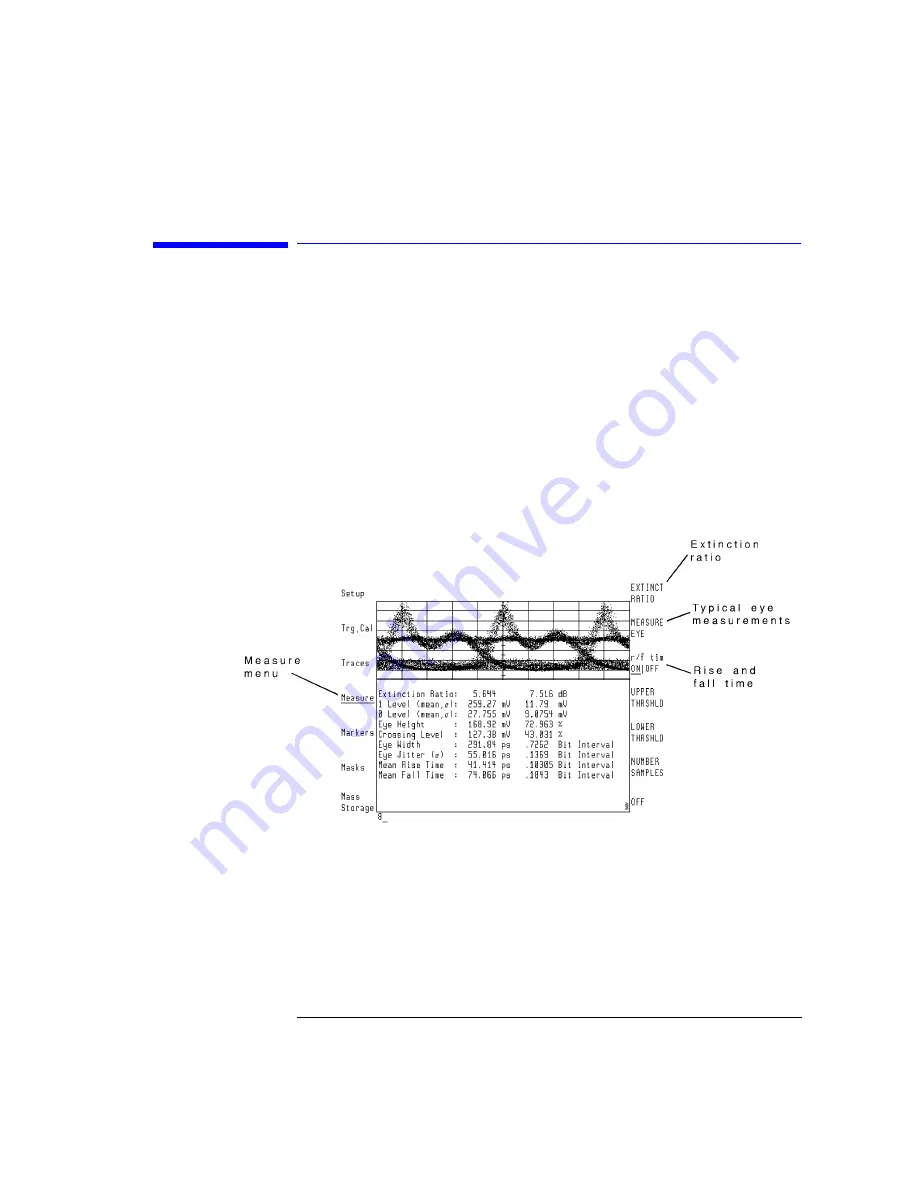
To perform the automatic eye-diagram measurements, use the Measure menu. 
With the exception of extinction ratio, these measurements must be per-
formed in eye mode. 

Automatic Measurements      

The Measure menu’s top two softkeys automatically start measurements: 

• EXTINCT RATIO
• MEASURE EYE 


• Use the EXTINCT RATIO softkey to automatically compute the extinction ratio 

in eye or eyeline modes. This measurement is a ratio of the most prevalent log-
ical one level divided by the logical zero level over one bit interval. When mak-
ing extinction ratio measurements in eyeline mode, the number of samples 
should be increased from the default of 1000 to approximately 20000. This in-
sures that a number of traces are evaluated to compute the extinction ratio. 

Summary of Contents for 71501D

Page 1: ...Agilent 71501D Eye Diagram Analysis User s Guide...

Page 2: ...which if not cor rectly performed or adhered to could result in damage to or destruction of the product Do not proceed beyond a cau tion sign until the indicated conditions are fully under stood and...

Page 3: ...ondition in which all means for protection are intact only WAR N I N G No operator serviceable parts inside Refer servicing to qualified service personnel To prevent electrical shock do not remove cov...

Page 4: ...71501D clean it thoroughly C AUT IO N This product is designed for use in Installation Category II and Pollution Degree 2 per IEC 61010 1C and 664 respectively C AUT IO N Always use the three prong ac...

Page 5: ...Pattern 2 27 Tutorial 9 Constructing a Low Pass Filter from a Transfer Function 2 30 Tutorial 10 Create a Vertical Histogram 2 36 Tutorial 11 Create a Horizontal Histogram 2 41 3 Eye Diagram Analyzer...

Page 6: ...nts 5 Specifications and Characteristics Vertical Specifications 5 3 Input Channel Specifications 5 4 Trigger Specifications 5 5 Trigger Specifications 5 6 Horizontal Specifications 5 7 Declaration of...

Page 7: ...1 Getting Started...

Page 8: ...perate similar to a high speed sampling oscilloscope such as the Agi lent 86100A Infiniium DCA The 71501D can perform eye diagram analysis such as extinction ratio testing and mask testing In addition...

Page 9: ...nstrument functions Each of these functions can also be accessed using the normal softkey menus If you have the custom keypad practice using it You will find that the time required for many of the pro...

Page 10: ...e Eye Diagram Personality Each time the 71501D is turned on the 70874A eye diagram analyzer person ality part number 70874 10001 must be loaded into memory This occurs automatically if the 70874A memo...

Page 11: ...tern modes Use the Setup menu s diagram softkey to select from one of three measure ment modes eye eyeline and pattern Features Available in Each Mode Eye Mode Eyeline Mode Pattern Mode Eye Measuremen...

Page 12: ...Diagram Analysis Eye Mode The eye mode displays traces using individual dots in a manner that is similar to conventional sampling oscilloscopes Use this mode for the following Typical eye diagram mea...

Page 13: ...gram Analysis Eyeline Mode Eyeline mode displays continuous traces Use this mode for the following Measure extinction ratio Measure laser turn on transition delay Examine laser overshoot Observe laser...

Page 14: ...esting Mask limit lines are displayed geometric shapes that define the acceptable limits and shape of an eye diagram The following figure shows a mask Use masks for pass fail testing and as an aid to...

Page 15: ...son filters These files are on the 71501D memory card Refer toChapter 9 Agilent 70820A User Corrections and Chapter 11 Agi lent 70820A Memory Cards Disks and RAM for information on user correc tions U...

Page 16: ...clock frequency pattern length and any divide ratios In the case of alternate configurations an appropriate sub menu will be displayed for the parameters that require manual updating N o t e A READ P...

Page 17: ...automatically selects the appropriate hardware gain and offset to maximize the signal at the analog to digital converter regardless of the input signal s amplitude Selecting the 10 MHz reference on I...

Page 18: ...Connect the Equipment 70841A B Pattern Generator and 70311A Signal Generator Modules 1 If you are using 70841A B pattern generator and 70311A signal generator modules with your eye diagram analyzer in...

Page 19: ...70311A make sure that the signal generator and 70820A microwave transition analyzer module share the same frequency reference Use the 10 MHz REF connectors on the rear panel of the 70820A Rear Panel...

Page 20: ...connector is not 6 dB press Trg Cal CH2 EXT ATTEN then enter the value of the attenuator Front Panel Cable Connections Cables SMA to SMA Channel 1 p n 8120 4948 SMA to SMA Channel 2 p n 8120 4948 SMB...

Page 21: ...rter use the connections shown in the following figure To protect the input connectors use adapters between the cables and the connectors The laser is the device being tested Cables SMA to SMA Channel...

Page 22: ...ye diagram analyzer Step 2 Load the Personality Automatically Load the Personality 1 Insert the eye diagram personality card into the front panel card slot of the microwave transition analyzer facing...

Page 23: ...Loading 70874 never shows The left side softkeys match those shown in the following figure Manually Load the Personality on page 1 17 70820A Module s Main Menu Manually Load the Personality 1 Insert...

Page 24: ...RD MENU The list of files should now be displayed 4 Turn the front panel knob to highlight the file AUTOST and then press LOAD FILE If you load the 70874 file by mistake the message 7386 memory over f...

Page 25: ...xplanation of the self guided screens If the screen looks like the figure on the right side of this page the first self guided screen is displayed Perform the following steps 1 Press 7084X if you are...

Page 26: ...gram Analysis First Self Guided Screen 3 Use the following self guided screen to indicate the 10 MHz frequency reference used Press INTERNL if the 70820A module is used as the reference Press EXTERNL...

Page 27: ...r s left side Setup menu is selected 5 If you have not already connect the cables to the instruments front panels follow the instructions shown Otherwise proceed with If you have not already connect t...

Page 28: ...rement Conditions Select the Mode 1 To select the mode press Setup diagram EYE EYELINE or PATTERN Select Single or Continuous Sweeps 2 Press the left side Trg Cal softkey 3 Select one of the following...

Page 29: ...igger or sync output enter 16 if the clock signal is divided by 16 9 Enter the pattern repetition length by pressing PATTERN LENGTH and enter the pattern repetition length The pattern repetition lengt...

Page 30: ...Refer to To Manually Set the Trigger Level on page 1 25 in this chapter 1 Turn on the power for both mainframes Wait until the start up routines are completed and the mainframes are ready for key pres...

Page 31: ...5 To return control to the eye diagram analyzer press DISPLAY NEXT INSTR 6 To return to the eye diagram analyzer personality menus press USER To Manually Set the Trigger Level If a pattern generator o...

Page 32: ...t Optional Step Save Instrument State as Preset State 1 Select the Traces menu and scale the screen to the displayed signal by pressing Traces AUTOSCALE 2 Save the current instrument state by pressing...

Page 33: ...ps for Setting Up Eye Diagram Analysis 3 The eye diagram is now ready for use To restore the factory instrument preset Restore the factory instrument preset by pressing MENU page 1 of 2 States more 1...

Page 34: ...Getting Started Steps for Setting Up Eye Diagram Analysis...

Page 35: ...2 Application Tutorials...

Page 36: ...torial 7 Default and Custom Mask or Limit Line Testing 2 23 Tutorial 8 Display the Data Pattern 2 27 Tutorial 9 Constructing a Low Pass Filter from a Transfer Function 2 30 Tutorial 10 Create a Vertic...

Page 37: ...eq 2 48832 GHz Clock Ampl 500 mV Clock Hi Lvl 0 V If you re performing these tutorials without the laser source and optical to electrical converter reduce the level of the data signal as shown in the...

Page 38: ...persistence mode on Refer to Chapter 3 Eye Diagram Ana lyzer Reference for an explanation of the available persistence modes 2 Enter the number of sweeps by pressing PERSIST SWEEPS and enter 8 3 Turn...

Page 39: ...laser s one and zero levels 4 Turn the laser off If you are measuring the pattern generator directly disconnect the input signal at channel 1 5 Perform the calibration by pressing Trg Cal OFFSET CAL C...

Page 40: ...URE EYE After a brief period of time the display should look like the following figure Refer to Chapter 3 Eye Diagram Analyzer Reference for definitions of each measurement listed on the screen Exampl...

Page 41: ...r the of samples A larger value gives more accuracy but increases the data acquisition time When making extinction ratio measurements in eyeline mode the number of samples should be increased from the...

Page 42: ...nnel and marker readouts to watts div 1 Set the analyzer to a known state by pressing INSTR PRESET Trg Cal CH1 EXT ATTEN responsivity value V Watt For example the following figure shows 350 V Watt ent...

Page 43: ...2 9 Application Tutorials Tutorial 2 Measure in Optical Power Units...

Page 44: ...ith a responsivity of 30 volts watt is used When making extinction ratio measurements in eyeline mode the number of samples should be increased from the default of 1000 to something on the order of 20...

Page 45: ...This is sometimes referred to as the dark level The offset calibration ensures accurate measurements of the laser s level 5 Turn the laser off If you are measuring the pattern generator directly disco...

Page 46: ...easure the extinction ratio press Measure NUMBER SAMPLES and enter 20000 EXTINCT RATIO Refer to the following figure Extinction Ratio Measurement on a Low Level Signal with Eye Filtering On Display th...

Page 47: ...OFF ON BIT INTVL and enter 1 2 Set the persistence to infinite by pressing Traces persist INFINIT Trg Cal 3 After several traces have been displayed press CONT STOP STOP Turn on the markers 4 Press X1...

Page 48: ...Application Tutorials Tutorial 4 Measure Laser Turn on Delay Laser Overshoot and Turn On Delay...

Page 49: ...eline mode is especially useful for measuring variations in laser turn on delay over shoot and ringing and for applying user frequency corrections The compati ble mode is eyeline Several Bessel Thomso...

Page 50: ...he Data Change to Eyeline Mode 1 Set the analyzer to a known state by pressing INSTR PRESET Traces persist VARIABL and enter 5 diagram EYELINE Notice the level of the laser overshoot and the turn on d...

Page 51: ...l knob to highlight the file a_bt248832 5 Load the file into user corrections by pressing LOAD FILE This file simulates a 4th order Bessel Thomson filter with a cutoff at three quarters of the bit rat...

Page 52: ...n the autoscale function on by pressing Traces AUTO SCALE The display should look like the following figure Notice that the laser overshoot is no longer visible due to the filtering effect of the user...

Page 53: ...ly Select the Mask 1 Set the analyzer to a known state by pressing INSTR PRESET 2 You can use your own hardware filter during this tutorial or load a software filter as described in the previous tutor...

Page 54: ...15 mask margin and turn margin testing on by pressing mask setup MASK MARGIN and enter 15 msk mar ON OFF ON This displays a second set of mask and limit lines for the 15 percent margin Errors for the...

Page 55: ...delay by pressing Setup BIT INTVL and enter 1 DELAY and enter 3 The mask will be offset to the right side of the display 9 Set the analyzer so testing will stop after two errors have occurred by press...

Page 56: ...fter two error traces have been accumulated Refer to the following figure Note that for this figure errors occur due to overshoot on a zero to one transition Turn off Mask Testing 13 Turn off error tr...

Page 57: ...hapes are provided for your use hexagon square equilateral triangle inverted equilateral triangle flat line You can stretch shrink or move any mask It is also easy to add additional points or delete u...

Page 58: ...edit the shape press edit Move a Point 4 To move a point select the point to be moved by pressing or 5 Select the direction to move by pressing move X Y Move the point by rotating the front panel knob...

Page 59: ...menu Begin a Test 15 Display the Masks Limits menu by pressing MENU page 1 of 2 Analyze masks limits 16 Select the trace for testing by pressing trace 17 If trace violations are to be counted as error...

Page 60: ...MENU page 1 of 2 Analyze masks limits define shapes edit SELECT the number of the mask or limit line to be erased 25 Erase the mask by pressing delete shapes DELETE CURRENT Remove all Displayed Masks...

Page 61: ...The compatible mode is Pattern Select Pattern Mode 1 Press INSTR PRESET 2 If you are using an 70841A B pattern generator connect the TRIGGER OUT signal to the 70820A module s RF INPUT 2 connector Thi...

Page 62: ...Y Each push of the step keys and gives a change in delay equal to exactly one bit This technique can also be used to step the X offset of the mask one bit at a time to check for mask violations at eac...

Page 63: ...Data Pattern 8 Set channel 2 by pressing CH2 is CLK OUT Notice that the diagram softkey annotation no longer indicates pattern mode and a note is displayed on the screen as shown in the following fig...

Page 64: ...useful as an example To aid in the construction of 4th order Bessel Thomson filters at other frequencies use the MAKEFILT program located on the IBASIC UTILITIES FOR 71500 SERIES memory card This car...

Page 65: ...races select TR1 display ON OFF OFF 4 Build the equation by pressing select TR2 input build eqn CLR END SEL EDT SEL 5 Turn the front panel to highlight the j operand and then press INSERT Continue usi...

Page 66: ...SEL Build the trace equation Notice the cursor has wrapped to the following line Be sure to include the last two right parenthesis characters shown on the last line 7 Turn auto scaling on by pressing...

Page 67: ...nob or numeric keypad 11 Continue by pressing Scale more 1 of 2 AUTO DELAY Traces store trace to user correct adaptiv ON OFF ON 12 Store the filter response in user corrections by pressing CHAN 1 USR...

Page 68: ...Application Tutorials Tutorial 9 Constructing a Low Pass Filter from a Transfer Function 14 Highlight UCORR1 using the knob 15 Continue by pressing RETURN Scale AUTO SCALE page 1 of 2 Calib user corr...

Page 69: ...n 16 To store the filter to a memory card press States more 1 of 2 mass storage 17 If the mass storage device needs to be selected refer to Saving to Mass Storage on page 3 34 18 Save the user correct...

Page 70: ...tical analysis on 2 Display the histogram menu by pressing page 1 of 2 Analyze histogm 3 Select the trace to perform the statistical analysis on by pressing trace Use the knob to select the desired tr...

Page 71: ...f samples to be taken for the histogram by pressing prev menu NUMBER SAMPLES of samples ENTER The default number of samples taken is 1000 7 To draw the vertical histogram press SINGLE ACQUIRE Data wil...

Page 72: ...mple points used to calculate the mean and standard deviation is the full screen 9 To change the limits press other UPPER LIMIT LIMIT 0 100 new upper limit value ENTER LOWER LIMIT LIMIT 0 100 new lowe...

Page 73: ...2 39 Application Tutorials Tutorial 10 Create a Vertical Histogram 10 To display a line indicating the location of the mean press results MEAN The mean and standard deviation values are also shown...

Page 74: ...Application Tutorials Tutorial 10 Create a Vertical Histogram 11 To display a line indicating the location of the standard deviation press STD DEV...

Page 75: ...statistical analysis on 2 Display the histogram menu by pressing page 1 of 2 Analyze histogm 3 Select the trace to perform the statistical analysis on by pressing trace Use the knob to select the desi...

Page 76: ...amples to be taken for the histogram by pressing prev menu NUMBER SAMPLES of samples ENTER The default number of samples taken is 1000 7 To draw the horizontal histogram press SINGLE ACQUIRE Data will...

Page 77: ...sample points used to calculate the mean and standard deviation is the full screen 9 To change the limits press other UPPER LIMIT LIMIT 0 100 new upper limit value ENTER LOWER LIMIT LIMIT 0 100 new l...

Page 78: ...Application Tutorials Tutorial 11 Create a Horizontal Histogram 10 To display a line indicating the location of the mean press results MEAN The mean and standard deviation values are also shown...

Page 79: ...2 45 Application Tutorials Tutorial 11 Create a Horizontal Histogram 11 To display a line indicating the location of the standard deviation press STD DEV...

Page 80: ...Application Tutorials Tutorial 11 Create a Horizontal Histogram...

Page 81: ...3 Eye Diagram Analyzer Reference...

Page 82: ...ements 3 3 Generating Histograms 3 7 Masks and Limit Lines 3 9 Eye Diagram Menu Maps 3 12 Agilent 70820A Menus 3 14 Controlling the Display 3 16 Calibrating the Eye Diagram Analyzer 3 23 Displaying Tr...

Page 83: ...keys automatically start measurements EXTINCT RATIO MEASURE EYE Use the EXTINCT RATIO softkey to automatically compute the extinction ratio in eye or eyeline modes This measurement is a ratio of the m...

Page 84: ...io The peaks of the histogram are used to set initial limits for the computation of the one and zero levels The initial mean and sigma of the one level is based on histogram data above the relative 50...

Page 85: ...horizontal histogram centered at the upper threshold point and a horizontal histogram centered at the lower threshold point on a falling edge of an eye diagram Measure Fast Amplitude and Phase Transi...

Page 86: ...RF source over the communications bus Share the same frequency reference as the RF source Channels Versus Traces The 70820A module has two input channels four traces and four trace mem ory registers...

Page 87: ...splay can show mean and standard deviation values of the histogram Histogram analysis is performed using the Histogram menu Press MENU the left side page 1 of 2 Analyze Histogm The 70820A menus perfor...

Page 88: ...lect histogram type 3 Enter the number of samples 4 Set limits for acquired data 5 Acquire the data 6 Establish limits for statistical analysis 7 View the mean and standard deviation Histogram data ca...

Page 89: ...and limit lines allow you to test the shape time or frequency versus amplitude of a displayed response Masks are closed polygon shapes Limit lines are lines Traces or measurement points that penetrate...

Page 90: ...ponse shapes masks and limit lines are ideal for pass fail testing on production lines You create save recall and edit limit lines using the masks limits menu Access this menu using the left side Anal...

Page 91: ...a set number of errors Testing ends after a set number of traces Use the test ON OFF softkey to start testing Testing stops whenever one of the following events occurs A set number of trace sweeps A s...

Page 92: ...Eye Diagram Analyzer Reference Eye Diagram Menu Maps Eye Diagram Menu Maps The two menu maps in this section graphically represent the eye diagram ana lyzer s softkey menus Setup and Trg Cal Menus...

Page 93: ...3 13 Eye Diagram Analyzer Reference Eye Diagram Menu Maps Traces Measure Markers Masks and Mass Storage Menus...

Page 94: ...de additional fea tures useful for running the eye diagram analyzer You will find the preview feature discussed in this chapter very useful It dis plays the programming command corresponding to the re...

Page 95: ...the softkeys located on the left side of the display to access the twelve major menus These softkeys are shown in two pages Press page 1 of 2 to view the second page of softkeys When the 70820A modul...

Page 96: ...d enter the number of bits to display Set the time delay by pressing Setup DELAY and enter the desired time delay To Measure in Optical Power Units The Trg Cal menu s CH1 EXT ATTEN and CH2 EXT ATTEN s...

Page 97: ...ndwidth operation can be used in both eyeline and pattern modes but not in eye mode 1 Extend the measurement bandwidth by pressing Setup diagram EYELINE or PATTERN The extended 40 GHz bandwidth cannot...

Page 98: ...menus by pressing USER Setup diagram EYELINE or PATTERN User corrections can not be applied in eye mode 3 Display a catalog of the files contained on the memory card by pressing Mass Storage Rotate t...

Page 99: ...ence Controlling the Display 4 Load the file by pressing LOAD FILE The file is loaded when user corrections loaded is displayed on the screen 5 Turn the user correction function on by pressing Trg Cal...

Page 100: ...menus are not displayed load the program as explained in Chapter 1 Getting Started To Preview Programming Commands Press MENU Config more 1 of 3 preview ON OFF ON For a demonstration of the Preview f...

Page 101: ...he clocks are dis played the indicated time and the display format When the mainframe is turned on the display sets the clock in the 70820A module This causes both clocks to indicate the same time Con...

Page 102: ...s set clock Enter the new value in the same format as displayed Control the Display s Clock 1 Press DISPLAY Misc clock If you want to turn the clock display on and off press CLOCK DISPLAY If you want...

Page 103: ...sometimes referred to as the dark level To perform an offset calibration 1 Turn the laser off and then press Trg Cal OFFSET CAL CONT The calibration takes about a minute to execute When the calibratio...

Page 104: ...front panel CALIBRATOR OUTPUT and channel 1 connectors 2 To calibrate the IF press MENU page 1 of 2 Calib IF calib CAL CH1 The calibration routine takes about 30 minutes to complete 3 Disconnect the...

Page 105: ...f each trace can be separately adjusted To automatically adjust the trace scale factor and ref erence level for optimum display simply press AUTO SCALE Signals are autoscaled once when the softkey is...

Page 106: ...ess Traces AUTO SCALE to automatically scale the selected trace or SCALE to manually set the scale Use the front panel knob or numeric keypad to change the displayed vertical scaling REF LEV POS POS t...

Page 107: ...rage average ON OFF ON Four Persistence Modes are Available The eye diagram analyzer offers four trace persistence selections These selections are located under the Traces menu s persist softkey and i...

Page 108: ...s N is set with the PERSIST SWEEPS every trace gets dimmer by one intensity level traces already at the dimmest level disappear altogether Lower values of N work best with this type of persistence typ...

Page 109: ...instead of color each time a dot falls on it There are 15 different levels of intensity In this mode EXIT GRADING must be used to return to normal instrument operation a Apply persistence by pressing...

Page 110: ...e displayed waveform For example you can use markers to measure the peak to peak difference in a laser s turn on time as measured on the eye diagram s crossing point Use the front panel knob or numeri...

Page 111: ...ion rates are provided To learn how to create your own custom masks refer to Chapter 2 Application Tutorials Test Results are Displayed During mask testing mask violations are displayed in the lower p...

Page 112: ...e displayed data To change the number of samples used for the histogram use the Measure menu s NUMBER SAMPLES function Display the Error Trace Use the err trc ON OFF softkey to display a trace that vi...

Page 113: ...3 33 Eye Diagram Analyzer Reference Applying Mask Testing The Mask Setup Submenu...

Page 114: ...rking with Files on page 3 40 The following list shows the types of data that can be saved as files Traces Measurement states Histograms Masks Limit lines Calibrations User corrections User menus Down...

Page 115: ...d slot and retry the operation RAM Disks RAM disks offer a convenient method of duplicating memory cards Refer to To Duplicate a Memory Card on page 3 41 Up to 16 internal RAM disks can be created The...

Page 116: ...e number is used for hard disk drives For reading diskettes the volume number should be 0 To Use a Memory Card 1 Insert the memory card into the front panel card slot of the microwave transition analy...

Page 117: ...ent to create a RAM disk For example enter the following BASIC statement INITIALIZE MEMORY 0 0 128 3 Select the internal RAM disk by pressing MENU page 1 of 2 States more 1 of 2 mass storage msi MEMOR...

Page 118: ...ve s left side slot 5 Enter the disk drive s volume number by pressing VOLUME NUMBER The volume number should be left at the default value of zero for floppy disk drives 6 Continue by pressing MENU pa...

Page 119: ...nging the battery when extra care is appropriate 1 Install the memory card into the 70004A display 2 On the front edge of the card locate the groove of the battery clip 3 Gently pry the battery clip o...

Page 120: ...the standard prefixes allows you to indicate files that have similar data For example the following figure shows a catalog of two mask files Each file has an additional prefix of Shape The additional...

Page 121: ...elect the memory card for use 2 Insert the memory card with the files into the front panel card slot 3 Press USER If the eye diagram analyzer personality is loaded press USER twice 4 Use a keyboard to...

Page 122: ...rect address using the numeric keypad To Save a File Use this procedure to save a file in the default memory To select default mem ory refer to Selecting and Formatting Memory on page 3 34 1 Display t...

Page 123: ...oftkey to remove characters from the command entry cursor to the end of the command To Recall a File Use this procedure to recall a file from the default memory To select default memory refer to Selec...

Page 124: ...fix press ENTER LINE Entering the prefix without a keyboard a Turn the front panel knob to move the character select cursor b Press SELECT CHAR to enter a character at the character select cursor c Pr...

Page 125: ...D ENTER LINE To Save an Instrument State 1 Set the eye diagram analyzer to the desired settings 2 Insert a ROM card into the front panel card slot 3 Save the instrument state by pressing Mass Storage...

Page 126: ...Limit Line File 1 To recall a mask limit line file press MENU page 1 of 2 States more 1 of 2 mass storage If the mass storage device needs to be selected refer to Selecting and Formatting Memory on p...

Page 127: ...oduced in eye or eyeline modes To Create a Print 1 Connect the printer to the display via an GPIB cable Be sure to connect the GPIB to the display s connector not to the connector on the 70820A microw...

Page 128: ...on the 70820A microwave transition analyzer module 2 The first time the plotter is used enter the plotter type and address by pressing DISPLAY Hard Copy plotter address HP IB TLK LSN to configure the...

Page 129: ...trical converters To create and use your own user corrections enter the User Correction menu This menu is located under the 70820A s Calib menu The microwave transi tion analyzer maintains two separat...

Page 130: ...ta cannot be removed you can modify their magnitude or phase values New lines of data are easily added Each line of data consists of FREQuency MAGNitude PHASE and path to next FREQ fields The path to...

Page 131: ...nnel for User Corrections Select a channel for user corrections by pressing MENU page 1 of 2 Calib user corr CH1 CH2 CH1 to select channel 1 CH1 CH2 CH2 to select channel 2 To Turn User Corrections On...

Page 132: ...editing lines of user correction data To view user correction data graphically at the same time it is created refer to Viewing User Correction Data on page 3 56 The SEL EDT softkey determines whether...

Page 133: ...ilent 70820A User Corrections The following two figures show the effect of selecting linear slope and flat types The trace graphically shows the filter With the exception of the path to next FREQ fiel...

Page 134: ...Enter a line of data by pressing MENU page 1 of 2 Calib user corr SEL EDT SEL New lines are added just above the highlighted line Use the front panel knob or arrow keys to highlight any field of the l...

Page 135: ...panel knob or arrow keys to highlight any field in the line you wish to delete 2 Delete the highlighted text by pressing other DELETE LINE To Select Flat Line Interpolation 1 Highlight the desired fi...

Page 136: ...cal The start and stop frequencies are the same This includes any frequency offset Set the Frequency Scale for Time Sweeps When the microwave transition analyzer is performing time sweeps the fre quen...

Page 137: ...the Traces menu press Traces 3 Select a trace and then press input 4 Use the front panel knob to scroll the menu bar to UCORR1 as shown in the following figure UCORR1 sets the trace to user correction...

Page 138: ...time sweep press the Main menu s SEC DIV softkey and enter the sweep time to set the stop frequen cy The formula to determine the sweep time is provided at the beginning of this section 8 To enter the...

Page 139: ...e an 46021A keyboard and keyboard cable To Save a User Correction File 1 Display the Mass Storage menu by pressing MENU page 1 of 2 States more 1 of 2 mass storage If the mass storage device needs to...

Page 140: ...ing Memory on page 3 34 2 Rotate the front panel knob to select highlight the desired file 3 Load the file by pressing LOAD FILE To Erase a User Correction File 1 To erase a mask limit line file press...

Page 141: ...orrection Calibrate the IF Verify the calibrator signal The Calibration Menu The automatic IF calibrations documented in this section ensure accurate measurements using the eye diagram analyzer RF cor...

Page 142: ...hese correction factors are loaded into nonvolatile memory at the factory You can prevent the use of RF correction factors during mea surements N o t e Eyeline and pattern modes are required RF correc...

Page 143: ...1 or channel 2 The following figure shows added delay on channel 2 Use the AUTO SKEW softkey to automatically compensate the delay on chan nel 2 Automatic skewing assumes two equal phase signals inpu...

Page 144: ...ransition analyzer module provides separate automatic IF cal ibration routines for channel 1 and channel 2 Each requires approximately 30 minutes to run For optimum performance you should perform the...

Page 145: ...MENU page 1 of 2 Calib IF calib CAL CH1 CAL CH1 The calibration routine takes about 30 minutes to complete 3 Disconnect the cable from channel 1 and connect it to the channel 2 connector 4 Repeat the...

Page 146: ...ew IF Correction Data Traces 1 Display the Traces menu by pressing MENU Traces 2 Turn on both trace 1 and trace 2 Set the input to trace 1 as channel 1 Set the input to trace 2 to channel 2 3 Display...

Page 147: ...2 Turn on both trace 1 and trace 2 Set the input to trace 1 as channel 1 Set the input to trace 2 to channel 2 3 Display the 100 kHz filter response of stage 0 by pressing page 1 of 2 Calib IF calib c...

Page 148: ...keys to scroll through the various hardware responses To View Calibration Data 1 Display the Traces menu by pressing MENU Traces 2 To make viewing the calibration date easier turn all displayed trace...

Page 149: ...lly runs whenever the microwave transition analyzer is turned on Perform the self test by pressing MENU page 1 of 2 Calib SELF TEST Controlling the Calibrator Signal For verification purposes the Cali...

Page 150: ...he Calibrator Signal On To turn the calibrator signal on press MENU page 1 of 2 Calib cal signal cal sig ON OFF ON To Change the Calibrator Frequency and Amplitude To change the calibrator frequency a...

Page 151: ...4 Programming Commands...

Page 152: ...view feature discussed in this chapter very useful It displays the programming command corresponding to the response received when most softkeys are pressed You will find information on the following...

Page 153: ...Command string variable directs the 70874C to perform an action Twelve possible command strings are documented in this chapter ALIGN BIT CLEAR DEFAULT DELAY DIAGRAM EXTIN MARGIN MARMSK MEAS PERSIST QU...

Page 154: ...asurement Notice that the MEAS command does not use the Param variable OUTPUT Mta PROG STR Command MEAS OUTPUT Mta PROG WAIT ENTER Mta A OUTPUT Mta PROG STR Response ENTER Mta Response OUTPUT Mta PROG...

Page 155: ...T ENTER Mta A OUTPUT Mta PROG STR Response ENTER Mta Response OUTPUT Mta PROG STAT CONT CLEAR The CLEAR command string clears the display for persistence mode or error trace mode CLEAR also restarts a...

Page 156: ...types STM 1 default mask for STM 1 STM 4 default mask for STM 4 STM 16 default mask for STM 16 OC 3 default mask for OC 3 OC 12 default mask for OC 12 OC 48 default mask for OC 48 Example OUTPUT Mta P...

Page 157: ...G STAT CONT DIAGRAM The DIAGRAM command string sets the diagram display to one of the follow ing types specified in the Param variable EYE displays eye pattern This is the standard display shown on di...

Page 158: ...tinction ratio measurement The Response variable is loaded with two floating point numbers The first number is the linear ratio The second number is the logarithmic value Values of Program Variables V...

Page 159: ...ting point number that spec ifies the percentage over standard mask to test The range of margin is 0 to 100 percent Example OUTPUT Mta PROG NUMB Param 25 6 OUTPUT Mta PROG STR Command MARGIN OUTPUT Mt...

Page 160: ...llowing eight measurements on the eye 1 mean 1 level 2 mean 0 level 3 eye height 4 crossing level 5 eye width 6 eye jitter 7 mean rise time 8 mean fall time The Response variable is loaded with eight...

Page 161: ...r maps are necessary for proper dis play and are available only with Instrument BASIC Command parameters include INF VAR COLGRAD MONOGRAD and OFF Each parameter has the following action INF turns on i...

Page 162: ...ing causes the eye diagram personality to terminate This command does not pause upon completion Example OUTPUT Mta PROG STR Command QUIT Values of Program Variables Variable Data Type Value Command st...

Page 163: ...5 Specifications and Characteristics...

Page 164: ...ess otherwise noted All specifications apply after the in strument s temperature has been stabilized after 1 hour continuous opera tion and self calibration routines have been run Unless otherwise not...

Page 165: ...cal Specifications Table 5 1 Vertical Specifications Bandwidth 3 dB 20 GHz extended BW off 40 GHz extended BW on dc accurachy 5 C from cal The larger of 2 of signal ampltiude or 500 V The larger of 1...

Page 166: ...and RF INPUT 2 are dc coupled Table 5 2 Input Channel Specifications Operation input range including dc offset 320 mB Maximum safe input voltage without damage 2 V pk pk Number of input channels 2 In...

Page 167: ...e 5 3 Trigger Specifications Operation input range including dc offset 320 mV Maximum safe input voltage without damage 2 Vpk pk Number of input channels 2 Input connectors a a Includes two 2 4 mm f t...

Page 168: ...Specifications and Characteristics Trigger Specifications Trigger Specifications Table 5 4 Trigger Specifications Trigger sensitivity dc 40 GHz 65 mV pk pk typical Jitter 2 5 ps rms...

Page 169: ...time measurement accuracy whichever is larger Time delay in eye mode clock frequencies 10 MHz Time delay in eyeline and pattern modes Pattern repetition frequeny 10 MHz Pattern repetition frequency 1...

Page 170: ...Specifications and Characteristics Declaration of Conformity Declaration of Conformity...

Page 171: ...ye diagram analyzer 3 23 calibration 70820A 3 61 data 3 66 date 3 65 IF 3 64 menu 3 62 offset 2 5 calibration menus 3 12 calibrator frequency amplitude 3 70 calibrator signal control 3 69 calibrator s...

Page 172: ...3 48 displaying traces 3 25 duplicate memory card 3 41 E edit a line of data 3 55 edit mask or limit line 2 24 enter a line of data 3 54 entering and editing user corrections 3 52 erase files 3 43 er...

Page 173: ...istogram selection 2 36 histogram vertical creation 2 36 histograms generating 3 7 horizontal histogram creation 2 41 I IF calibration 3 64 improve the sensitivity in eyeline mode 3 17 industry standa...

Page 174: ...18 memory card formatting 3 37 memory cards 3 34 menus 70820A 3 14 Agilent 70820A 3 14 averaging 3 27 calibration 3 62 eye diagram 3 12 histogram 3 7 left side 3 15 maps 3 12 mask setup 3 33 module ma...

Page 175: ...1 22 select the pattern generator settings 1 23 select trigger source 1 22 selecting memory 3 34 self guided screen 1 20 self test 3 69 sensitivity in eyeline mode 3 17 set up measurement conditions 1...

Page 176: ...to data example 2 16 files 1 9 modes available 1 5 user correction file erase 3 60 recalling 3 60 saving 3 59 user correction files 3 18 user correction files 3 18 user corrections 70820A 3 49 applyi...

Reviews: