


Installation Guide: Flame Ionization Detector (FID)
13
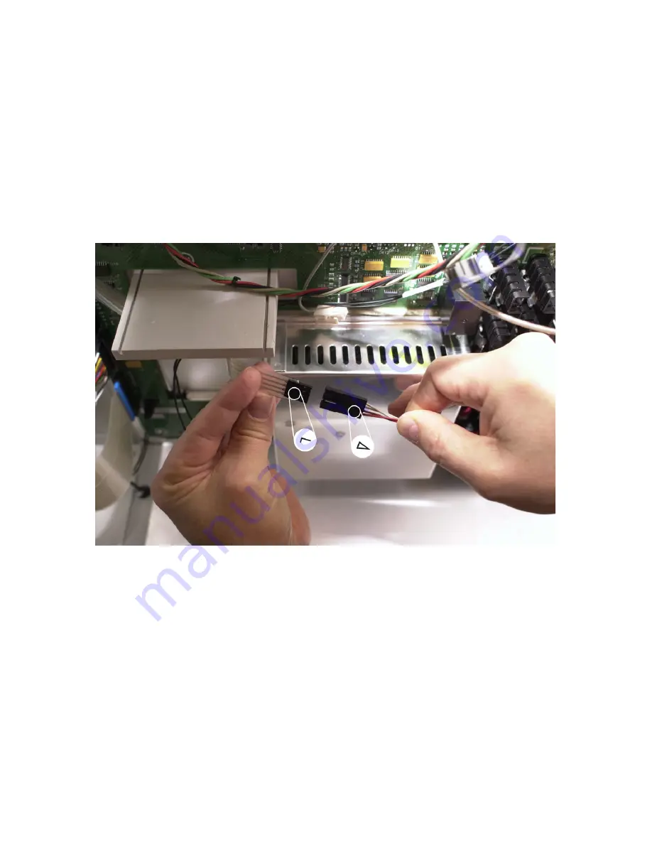
•
The two connectors must be joined in the proper
orientation for correct ignitor operation; align the small
triangle found on the FID ignitor extension cable
connector with the number
1
found on the ribbon cable
connector, then push the two connectors fully together.
3
In the flow control (left side) portion of the GC, note labeling
and wire colors for the four separate "push-on" connectors
located near the detector flow control modules:
•
If the previously-installed flow module is in the upper
detector position, select the red pair of wires (labeled
"FRONT") and push each connector onto an electrical
terminal at the back of the flow module (no polarity).