


14 Verification
Output Checkout
1.
Make sure that there is no load connected to the output connector by removing the output connector assembly.
2.
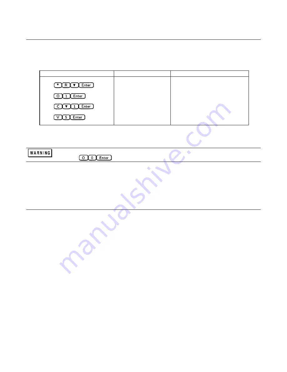
Check the basic voltage functions and module communications as shown in following table:
Action
Keyboard Display
Explanation
Press
*RST
Resets the Modular Power System
Press
:OUTP ON
Enables the output
Press
:CURR 1
Sets the output current to 1 A
Press
:VOLT 5
Sets the output voltage to 5 V
3.
The keyboard display should now be in meter mode indicating the voltage and status of the dc power module:
Disable the output prior to connecting a load.
Press
In Case of Trouble
If the keyboard and module displays do not read the correct voltage, check the operation of the module. Refer to the
"Performance Measurement" section of the Agilent
Series 66lxxA Power Modules Service Manual
.
Problem Not Identified
If after performing the checkout procedures you were unable to isolate the problem, refer to the "Overall Troubleshooting"
procedure in Chapter 4. The overall troubleshooting procedure will verify whether the mainframe is at fault and will isolate
the problem to a functional block.
Summary of Contents for 66000A
Page 20: ......
Page 23: ...Troubleshooting 23 Figure 4 1 Overall Troubleshooting Sheet 1 of 7...
Page 24: ...24 Troubleshooting Figure 4 1 Overall Troubleshooting Sheet 2 of 7...
Page 25: ...Troubleshooting 25 Figure 4 1 Overall Troubleshooting Sheet 3 of 7...
Page 26: ...26 Troubleshooting Figure 4 1 Overall Troubleshooting Sheet 4 of 7...
Page 27: ...Troubleshooting 27 Figure 4 1 Overall Troubleshooting Sheet 5 of 7...
Page 28: ...28 Troubleshooting Figure 4 1 Overall Troubleshooting Sheet 6 of 7...
Page 29: ...Troubleshooting 29 Figure 4 1 Overall Troubleshooting Sheet 7 of 7...
Page 30: ...30 Troubleshooting Figure 4 2 Bias Troubleshooting Sheet 1 of 2...
Page 31: ...Troubleshooting 31 Figure 4 2 Bias Troubleshooting Sheet 2 of 2...
Page 32: ...32 Troubleshooting Figure 4 3 ROM Microprocessor Troubleshooting...
Page 43: ...TP 0 TP 1 TP 2 TP 4 TP 5 TP 8 TP 7 TP 9 TP10 TP11 TP12 TP13 COM TP14 TP 3 TP 6...
Page 44: ......
Page 45: ......
Page 46: ......
Page 47: ......
Page 48: ......
Page 50: ......