


3-37
Triggering the Oscilloscope
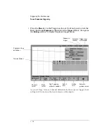
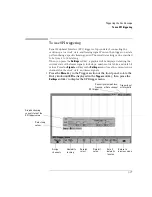
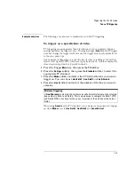
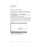
To use SPI triggering
To use SPI triggering
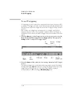
Serial Peripheral Interface (SPI) trigger setup consists of connecting the
oscilloscope to a clock, data, and framing signal. You can then trigger on a data
pattern during a specific framing period. The serial data string can be specified
to be from 4 to 32 bits long.
When you press the
Settings
softkey, a graphic will be displayed showing the
current state of the frame signal, clock slope, number of data bits, and data bit
values. Press the
Signals
softkey in the
Settings
menu to see the current source
channels for the clock, data, and frame signals.
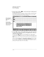
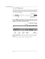
• Press the
More
key in the Trigger section of the front panel, rotate the
Entry knob until
SPI
is displayed in the
Trigger
softkey, then press the
Settings
softkey to display the SPI trigger menu.
Assign
channels
# data bits
in string
Data bit
select
Set all
data bits
to value
Trigger level
or threshold
Currently selected Clock,
Framing, or Data channel
SPI trigger
Return to
previous menu
Data bit
value
Data string
values
Graphic showing
current state of the
SPI trigger setup
Summary of Contents for 54621A
Page 4: ...iv ...
Page 10: ...Contents 6 ...
Page 11: ...1 Getting Started ...
Page 38: ...1 28 ...
Page 39: ...2 Front Panel Overview ...
Page 63: ...3 Triggering the Oscilloscope ...
Page 117: ...4 MegaZoom Concepts and Oscilloscope Operation ...
Page 171: ...5 Making Measurements ...
Page 222: ...5 52 Making Measurements Making overshoot and preshoot measurements ...
Page 223: ...6 Utilities ...
Page 239: ...7 Performance Characteristics ...
Page 250: ...7 12 Performance Characteristics Agilent 54620 series Performance Characteristics ...
Page 260: ...7 22 ...