8 Installation Note 5967-8554
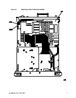
16. Attach the cable from the rear-panel connector labeled GATE TRIGGER INPUT to A16J501. See
17. Attach the cable from the rear-panel connector labeled GATE TRIGGER OUTPUT to A16J500. See
18. Reattach I/O board to CPU. Be careful not to pinch the SMB cable.
19. If the instrument has the dual I/O option, then it should be reattached. Make sure that the
connector is properly aligned, then firmly push into place. Replace the five screws attaching the
dual I/O to the rear panel.
CAUTION
Be careful not to bend or misalign the connector pins.
Replacing the Instrument Cover
CAUTION
To prevent damage when replacing the instrument cover, place a soft cloth or
towel between the work surface and the front panel.
Ensure cables do not bind between the instrument cover and the analyzer internal
assemblies.
20. Carefully place the analyzer on the work surface with the front panel facing down.
21. Replace the instrument cover assembly. The seam of the cover should be on the bottom side of the
analyzer.
22. Tighten the four rear-feet screws with a 4-mm hex wrench.
23. Replace the four screws and washers attaching the instrument cover assembly to the rear frame.
Contacting Agilent Technologies
1. If the CPU board does not have J501 and J500, order the 08590-60361 CPU kit for a compatible
CPU board.
2. To complete the Option 105 upgrade process refer to the Web at http://mktwww.soco.agilent.com/
field/service/signal/8590/105revb.htm to receive a complete set of instructions or call (707) 577-6801.
3. For detailed information about the 8590 Series firmware history, look on the Web at http://
mktwww.soco.agilent.com/field/service/signal/8590/firmhist.htm. The two different firmware kits
are noted on this web page.


