6
Installation Note 5967-8554
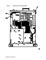
Figure 2
Gate Trigger Input and Gate Output
11. This installation kit comes with two long cables and two hex nuts. Install the cable with the #6 label
through the rear-panel GATE TRIGGER INPUT (1) opening. Use a hex nut to attach the cable to
the rear panel. Tighten the hex nut with the hex wrench.
12. Install the other cable with the #0 label through the rear-panel GATE OUTPUT (2) opening. Use a
hex nut to attach the cable to the rear panel. Tighten the hex nut with the hex wrench.
13. Remove the 4 screws attaching the Dual I/O interconnect board A40 to the CPU and remove the I/O
board.
14. Route the SMB cable ends to enable them to attach to A16J501 and A16J500.
NOTE
If J501 and J500 do not exist on the CPU, you will need to order a CPU Board Kit.
Refer to Contacting Agilent Technologies section of this document.
15. Being careful not to pinch or damage any of the cables, reattach the rear panel assembly to the
chassis of the analyzer.


