Theory of Operation
8
16901A Logic Analysis System Service Guide
95
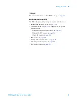
Voltage Rail Monitor
All six voltage rails are continuously
monitored for an under voltage fault condition. This could be
caused by such things as a failed power supply or a short
circuit within the instrument. When detected, both power
supplies are immediately shut down. At power up, there is a
one second time delay to allow the power to stabalize before
the monitoring circuit is enabled.
Overtemp Monitor
A temperature monitoring circuit protects
the instrument from thermal damage due to things such as
failed fans or blocked frame vents. The circuit first notifies
the CPU of a problem which then prompts the user with a
warning message and initiates a soft power down. If the soft
power down fails, a forced power down is initiated after
about two minutes.
Fan Control
The instrument uses a pair of 24 V fans driven
from a DC/DC boost converter circuit. This circuit creates a
linear voltage ramp from 12 V to 24 V across the operating
temperature range. The purpose of this circuit is to increase
air flow as needed while maintaining the lowest possible fan
noise.
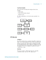
Front Panel Assembly
The front panel assembly is composed of two PC boards
comprising three independently operating sub- systems. The
two PC boards are the front panel interface board and the
keypad board. The three front panel sub- systems are:
•
Front panel keypad board.
•
Front panel interface board.
•
Front panel touch screen.
Front Panel Keypad Board
The front panel switches consist of five buttons and one
digital encoder, the knob. When a button is pressed and
released, or the knob turned, a series of codes are sent back
to the module FPGA. When the module FPGA receives a
front panel code, an interrupt is sent to the system CPU.
The resulting ISR will read the code and act on it.
The module FPGA was used as a convenient place to put
this logic. This logic operates independently of the module
backplane logic also within the module FPGA.
Summary of Contents for 16901A
Page 1: ...Agilent Technologies Agilent 16901A Logic Analysis System Service Guide...
Page 6: ...6 16901A Logic Analysis System Service Guide...
Page 10: ...10 16901A Logic Analysis System Service Guide Contents...
Page 18: ...18 16901A Logic Analysis System Service Guide 2 Preparing for Use...
Page 22: ...22 16901A Logic Analysis System Service Guide 3 Testing Performance...
Page 42: ...42 16901A Logic Analysis System Service Guide 5 Troubleshooting...
Page 102: ...102 16901A Logic Analysis System Service Guide 8 Theory of Operation...

