


74
Chapter 5: Troubleshooting
To test the cables
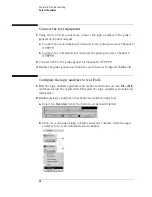
Connect the test equipment
1
Using two 2 x 9 test connectors, connect the logic analyzer to the pulse
generator channel outputs.
a
Connect the even-numbered channels to the pulse generator Channel 2
OUTPUT.
b
Connect the odd-numbered channels the pulse generator Channel 2
OUTPUT.
2
Connect Clk1 to the pulse generator Channel 2 OUTPUT.
3
Enable the pulse generator Channel 1 and Channel 2 outputs (LEDs off).
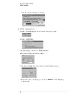
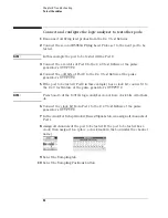
Configure the logic analyzer to test Pod 1
1
Exit the logic analysis application (from the main menu, choose
File
→
Exit
)
and then restart the application. This puts the logic analysis system into its
initial state.
2
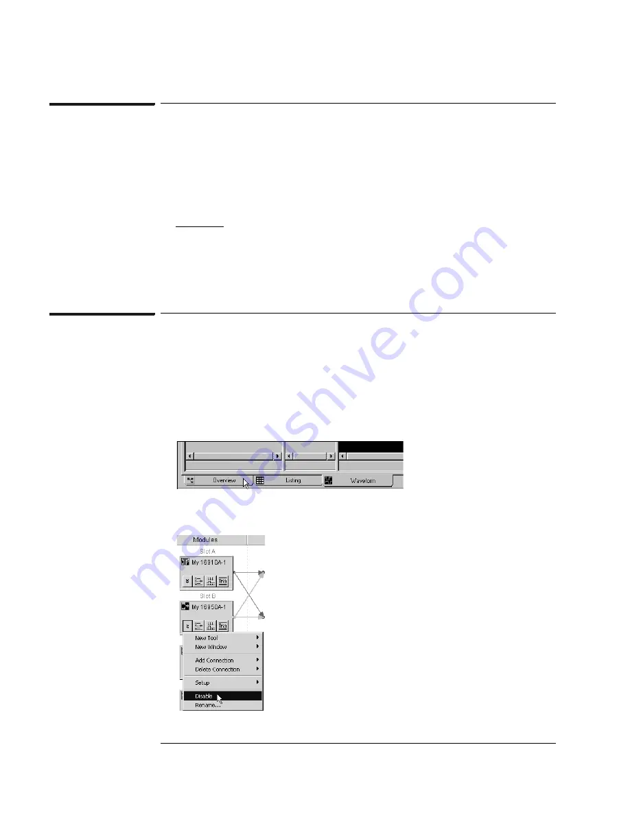
Disable all logic analyzers other than the analyzer under test.
a
Select the
Overview
tab at the bottom of the main window.
b
Click on each unused logic analyzer and select disable. Only the logic
analyzer to be tested should remain enabled.
Summary of Contents for 16900 Series
Page 3: ...3 Chapter The 16910A Logic Analyzer The 16911A Logic Analyzer...
Page 8: ...8 Contents...
Page 14: ...14 Chapter 1 General Information...
Page 18: ...18 Chapter 2 Preparing for Use...
Page 61: ...61 4 Calibrating This chapter gives you instructions for calibrating the logic analyzer...
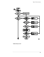
Page 65: ...65 Chapter 5 Troubleshooting Troubleshooting Flowchart 1...
Page 66: ...66 Chapter 5 Troubleshooting Troubleshooting Flowchart 2...
Page 82: ...82 Chapter 5 Troubleshooting To test the cables 18 Return to the troubleshooting flow chart...
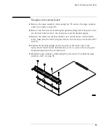
Page 94: ...94 Chapter 7 Replaceable Parts 16910A Exploded View Exploded view of the 16910A logic analyzer...
Page 95: ...95 Chapter 7 Replaceable Parts 16911A Exploded View Exploded view of the 16911A logic analyzer...
Page 96: ...96 Chapter 7 Replaceable Parts...
Page 102: ...102 Index...


