


73
Chapter 5: Troubleshooting
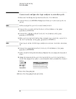
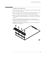
To test the cables
To test the cables
This test allows you to functionally verify the logic analyzer cable and the flying
lead probe of any of the logic analyzer pods. Only one probe and cable can be
tested at a time. Repeat this test for each probe and cable to be tested. Two
Flying Lead Probes are required if you need to test pods other than Pod 1
because the clock from Pod 1 will be used to acquire data.
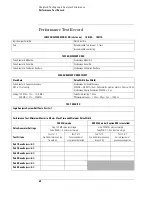
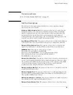
Equipment Required
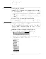
Set up the test equipment
1
If you have not already done so, do the procedure “Perform System Self-
Tests” on page 30.
2
Set up the pulse generator.
a
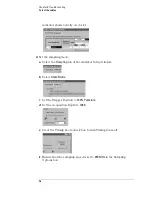
Set up the pulse generator according to the following table:
Pulse Generator Setup
Equipment
Critical Specification
Recommended Model/Part
Pulse Generator
40 MHz, 3 ns pulse width,
< 600 ps rise time
8133A Option 003
2 x 9 Test Connectors
(Qty 2)
no substitute
See “To Assemble the 2 x 9 Test
Connectors” on page 71.
SMA m-m adapter
(Qty 2)
Johnson 142-0901-811 SMA Plug
to Plug or similar
Flying Lead Probe
(Qty 2)
no substitute
HP or Agilent E5383A
Timebase
Pulse Channel 2
Trigger
Pulse Channel 1
Mode: Int
Mode: Pulse
÷
1
Disable (LED on)
Doesn’t matter, not used in
this test.
Freq: 40
MHz
Delay: (not available in pulse
mode)
Width: 3 ns
Ampl: 3 V
Offs: 1.5 V
Output: Enable (LED off)
Comp: Normal (LED off)
Limit: Off (LED off)
Output: Enable (LED off)
Summary of Contents for 16900 Series
Page 3: ...3 Chapter The 16910A Logic Analyzer The 16911A Logic Analyzer...
Page 8: ...8 Contents...
Page 14: ...14 Chapter 1 General Information...
Page 18: ...18 Chapter 2 Preparing for Use...
Page 61: ...61 4 Calibrating This chapter gives you instructions for calibrating the logic analyzer...
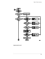
Page 65: ...65 Chapter 5 Troubleshooting Troubleshooting Flowchart 1...
Page 66: ...66 Chapter 5 Troubleshooting Troubleshooting Flowchart 2...
Page 82: ...82 Chapter 5 Troubleshooting To test the cables 18 Return to the troubleshooting flow chart...
Page 94: ...94 Chapter 7 Replaceable Parts 16910A Exploded View Exploded view of the 16910A logic analyzer...
Page 95: ...95 Chapter 7 Replaceable Parts 16911A Exploded View Exploded view of the 16911A logic analyzer...
Page 96: ...96 Chapter 7 Replaceable Parts...
Page 102: ...102 Index...


