


54
Chapter 3: Testing Logic Analyzer Performance
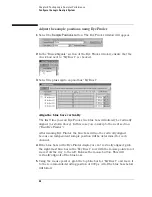
Test the Remaining Pods in 250 Mb/s Mode
Test the Remaining Pods in 250 Mb/s Mode
1
Perform the normal and complement tests for each additional pod on the
logic analyzer, changing the connection to the pod, channel assignments,
thresholds, etc. as appropriate. Test using clock Clk3 for Pod 3, clock Clk4
for Pod 4, etc. Upon completion, the logic analyzer is completely tested in
the 250 Mb/s mode. The 16910A has six pods; the 16911A has four pods.
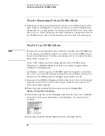
Test Pod 1 in 500 Mb/s Mode
NOTE:
If option 500 is not installed on the 16910/11A module, then 250 MHz will
be the only speed available. In this case, write “n/a” in the 500Mb/s mode
boxes in the Performance Test Record and proceed to “Conclude the State
Mode Tests” on page 59.
Clock “Clk1” will be used for testing all pods in the 500 Mb/s mode.
Therefore two E5383A Flying Lead Probe sets will be required when
testing the remaining pods.
You will use a test frequency of 125 MHz (plus test margin) to determine
the correct eye in the Eye Finder window. Then you will increase the test
frequency to 250 MHz (plus test margin) and perform the test.
1
Disconnect the E5383A Flying Lead Probe from Pod 6 of the 16910A logic
analyzer (or from Pod 4 of the 16911A logic analyzer) and connect it to
Pod 1 of the logic analyzer.
2
From the Logic Analysis System main menu, select
Setup
→
My
1691xA
→
Timing/State (Sampling)...
3
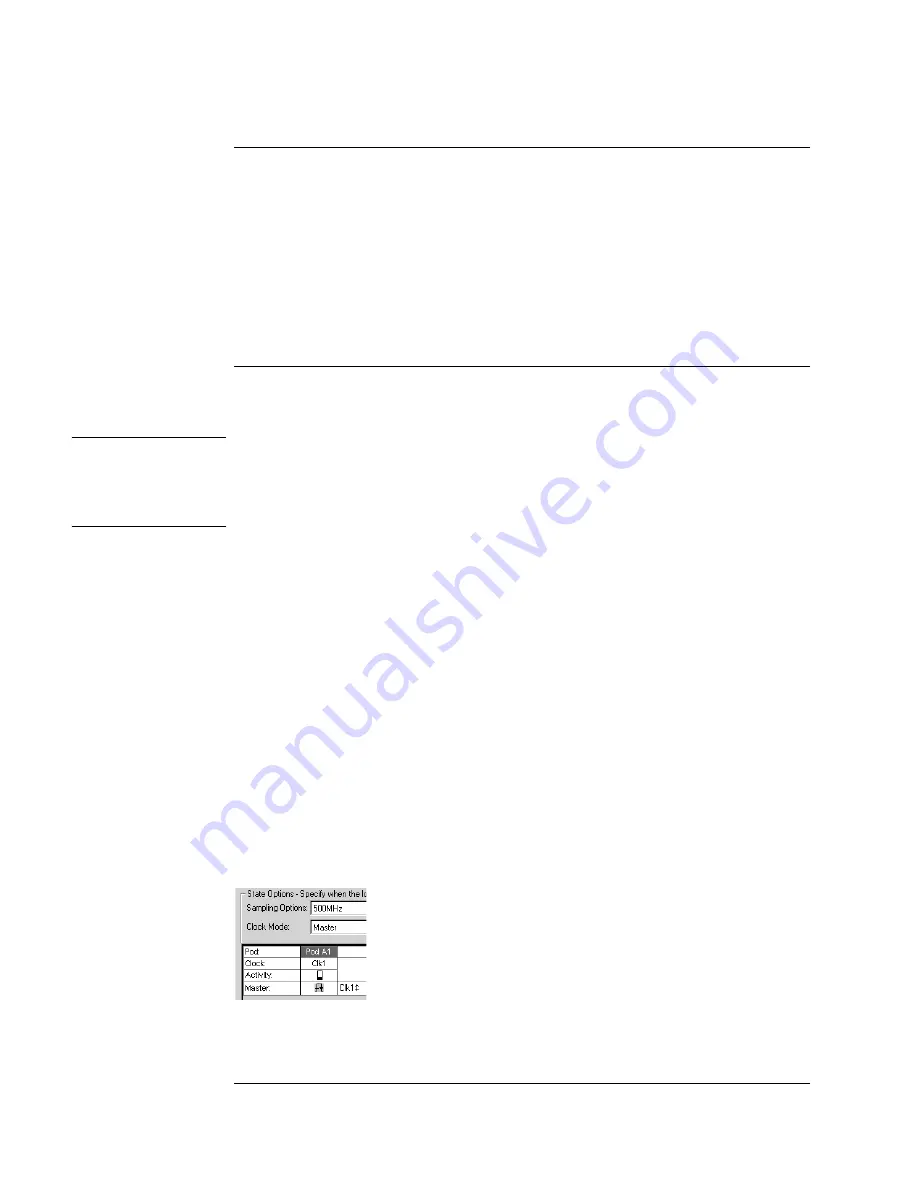
In the State Options section, Sampling Options field, select the “500 MHz”
mode. The clock mode will change to “Both Edges”. No other mode is
available.
4
In the logic analyzer’s Buses/Signals window, unassign all bits.
Summary of Contents for 16900 Series
Page 3: ...3 Chapter The 16910A Logic Analyzer The 16911A Logic Analyzer...
Page 8: ...8 Contents...
Page 14: ...14 Chapter 1 General Information...
Page 18: ...18 Chapter 2 Preparing for Use...
Page 61: ...61 4 Calibrating This chapter gives you instructions for calibrating the logic analyzer...
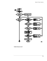
Page 65: ...65 Chapter 5 Troubleshooting Troubleshooting Flowchart 1...
Page 66: ...66 Chapter 5 Troubleshooting Troubleshooting Flowchart 2...
Page 82: ...82 Chapter 5 Troubleshooting To test the cables 18 Return to the troubleshooting flow chart...
Page 94: ...94 Chapter 7 Replaceable Parts 16910A Exploded View Exploded view of the 16910A logic analyzer...
Page 95: ...95 Chapter 7 Replaceable Parts 16911A Exploded View Exploded view of the 16911A logic analyzer...
Page 96: ...96 Chapter 7 Replaceable Parts...
Page 102: ...102 Index...


