


59
Using the Logic Analyzer
Using the Analyzer Menus
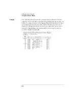
To create a symbol
Symbols are alphanumeric mnemonics that represent specific data
patterns or ranges. When you define a symbol and set the base type to
Symbol in the Listing menu, the symbol is displayed in the data listing
where the bit pattern would normally be displayed. The symbols also
appear in the Waveform menu when you view a label in bus form.
Symbols allow you to quickly identify data of interest.
To create a symbol, use the following procedure.
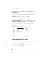
1
In the Analyzer Format menu, select Symbols.
The symbol table menu appears. The symbol table is where all user
symbols are created and maintained. If you get a message, "No labels
specified," check that you have at least one label turned on with
channels assigned to it.
2
In the Symbol menu, select the Label field. In the pop-up menu,
select the label that contains the channel groups you want.
When you open the symbol table menu, the Label field displays the
name of the first active label.
If the label you want does not appear in the pop-up menu, the label is
probably off. Return to the Format menu, select the label you want,
and select Turn Label On. Another possibility is that the label is on the
other analyzer. The two analyzers manage resources separately.
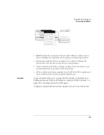
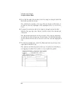
3
Select the Base field. In the pop-up menu, select the base for the
pattern.
In this example, binary is used because CYCLE only contains three
channels.
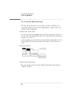
4
Select the field below Symbol. Select Add a Symbol, type in the
symbol name, then press Done.
Summary of Contents for 1670E Series
Page 6: ...6 In This Book...
Page 26: ...26 Contents...
Page 27: ...27 Section 1 Logic Analyzer...
Page 28: ...28...
Page 29: ...29 1 Logic Analyzer Overview...
Page 39: ...39 2 Connecting Peripherals...
Page 49: ...49 3 Using the Logic Analyzer...
Page 72: ...72 Using the Logic Analyzer The Inverse Assembler...
Page 73: ...73 4 Using the Trigger Menu...
Page 101: ...101 5 Using the Oscilloscope...
Page 151: ...151 6 Using the Pattern Generator...
Page 199: ...199 7 Triggering Examples...
Page 237: ...237 8 File Management...
Page 249: ...249 9 Logic Analyzer Reference...
Page 360: ...360 Logic Analyzer Reference The Compare Menu...
Page 361: ...361 10 System Performance Analysis SPA Software...
Page 397: ...397 11 Logic Analyzer Concepts...
Page 430: ...430 Logic Analyzer Concepts The Analyzer Hardware Oscilloscope board theory Oscilloscope board...
Page 439: ...439 12 Troubleshooting the Logic Analyzer...
Page 455: ...455 13 Specifications...
Page 471: ...471 14 Operator s Service...
Page 479: ...479 Operator s Service Troubleshooting Troubleshooting Flowchart 2...
Page 491: ...491 Section 2 LAN...
Page 492: ...492...
Page 493: ...493 15 Introducing the LAN Interface...
Page 497: ...497 16 Connecting and Configuring the LAN...
Page 506: ...506 Connecting and Configuring the LAN Connecting and Configuring the LAN...
Page 507: ...507 17 Accessing the Logic Analyzer File System Using the LAN...
Page 515: ...515 18 Using the LAN s X Window Interface...
Page 527: ...527 19 Retrieving and Restoring Data Using the LAN...
Page 539: ...539 20 Programming the Logic Analyzer Using the LAN...
Page 546: ...546 Programming the Logic Analyzer Using the LAN Programming the Logic Analyzer Using the LAN...
Page 547: ...547 21 LAN Concepts...
Page 555: ...555 22 Troubleshooting the LAN Connection...
Page 580: ...580 Troubleshooting the LAN Connection Getting Service Support...
Page 581: ...581 Section 3 Symbol Utility...
Page 582: ...582...
Page 583: ...583 23 Symbol Utility Introduction...
Page 588: ...588 Symbol Utility Introduction Symbol Utility Introduction...
Page 589: ...589 24 Getting Started with the Symbol Utility...
Page 597: ...597 25 Using the Symbol Utility...
Page 609: ...609 26 Symbol Utility Features and Functions...


