


141
Using the Oscilloscope
The Scope Marker Menu
Voltage Markers options
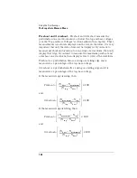
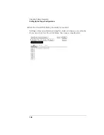
When you select the V Markers field on the display, a pop-up menu
appears. When you select the On field in the pop-up to turn Voltage
Markers On, you can manually move the Va and Vb markers to make
voltage measurements.
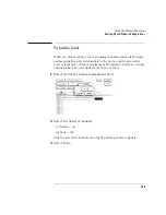
When you select the On field in the V Markers menu, five new fields
appear to the right of the V Markers field: Va On, Va Volts, Vb On, Vb
Volts, and Va to Vb fields. These fields allow you to position the Va
marker and the Vb marker by entering channel numbers and voltage
levels for these markers.
If you turn the voltage markers on while the time markers are also
turned on, the voltage levels that correspond to the time marker
waveform crossings will be deleted from the channel label field. If you
turn the voltage markers off while the time markers are turned on, the
voltage levels that correspond to the time marker waveform crossings
will appear in the channel label field.
Va On field
The Va marker is shown on the waveform display as a horizontal
dashed line.
The Va On field assigns the Va marker to one of the oscilloscope
acquisition channels. The default channel is channel 1.
The channel selected for assignment to the Va marker does not have to
be displayed in the waveform area. If the selected waveform is not in
the waveform area of the screen, the Va marker will not be displayed. If
there are multiple occurrences of the selected waveform in the
waveform area of the screen, only the uppermost occurrence of the
waveform will display the Va marker.
Summary of Contents for 1670E Series
Page 6: ...6 In This Book...
Page 26: ...26 Contents...
Page 27: ...27 Section 1 Logic Analyzer...
Page 28: ...28...
Page 29: ...29 1 Logic Analyzer Overview...
Page 39: ...39 2 Connecting Peripherals...
Page 49: ...49 3 Using the Logic Analyzer...
Page 72: ...72 Using the Logic Analyzer The Inverse Assembler...
Page 73: ...73 4 Using the Trigger Menu...
Page 101: ...101 5 Using the Oscilloscope...
Page 151: ...151 6 Using the Pattern Generator...
Page 199: ...199 7 Triggering Examples...
Page 237: ...237 8 File Management...
Page 249: ...249 9 Logic Analyzer Reference...
Page 360: ...360 Logic Analyzer Reference The Compare Menu...
Page 361: ...361 10 System Performance Analysis SPA Software...
Page 397: ...397 11 Logic Analyzer Concepts...
Page 430: ...430 Logic Analyzer Concepts The Analyzer Hardware Oscilloscope board theory Oscilloscope board...
Page 439: ...439 12 Troubleshooting the Logic Analyzer...
Page 455: ...455 13 Specifications...
Page 471: ...471 14 Operator s Service...
Page 479: ...479 Operator s Service Troubleshooting Troubleshooting Flowchart 2...
Page 491: ...491 Section 2 LAN...
Page 492: ...492...
Page 493: ...493 15 Introducing the LAN Interface...
Page 497: ...497 16 Connecting and Configuring the LAN...
Page 506: ...506 Connecting and Configuring the LAN Connecting and Configuring the LAN...
Page 507: ...507 17 Accessing the Logic Analyzer File System Using the LAN...
Page 515: ...515 18 Using the LAN s X Window Interface...
Page 527: ...527 19 Retrieving and Restoring Data Using the LAN...
Page 539: ...539 20 Programming the Logic Analyzer Using the LAN...
Page 546: ...546 Programming the Logic Analyzer Using the LAN Programming the Logic Analyzer Using the LAN...
Page 547: ...547 21 LAN Concepts...
Page 555: ...555 22 Troubleshooting the LAN Connection...
Page 580: ...580 Troubleshooting the LAN Connection Getting Service Support...
Page 581: ...581 Section 3 Symbol Utility...
Page 582: ...582...
Page 583: ...583 23 Symbol Utility Introduction...
Page 588: ...588 Symbol Utility Introduction Symbol Utility Introduction...
Page 589: ...589 24 Getting Started with the Symbol Utility...
Page 597: ...597 25 Using the Symbol Utility...
Page 609: ...609 26 Symbol Utility Features and Functions...


