background image

21

USING THE LCD DISPLAY

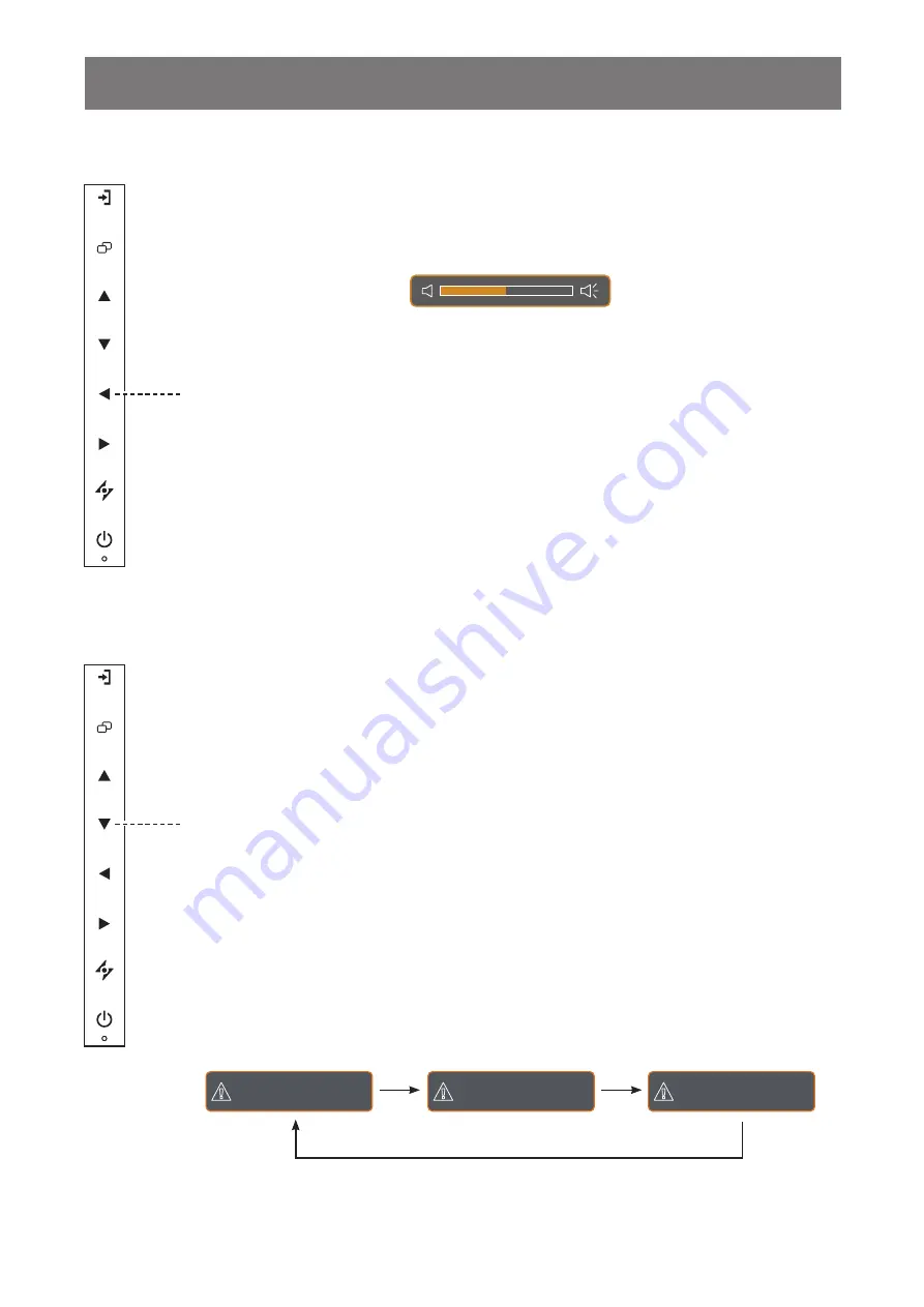
3.3 Adjusting the Volume

3.3.1    Muting the Audio

Press the 

u

 and 

t

 buttons simultaneously to mute or unmute the audio.

3.4 Choosing Your Preferred Picture Settings

Press the 

t

 button to call out the volume bar.

2


Press the 

u

 button to increase volume or the 

t

 button to decrease volume.

Hot Key: 

Audio Volume Adjustment

Hot Key: 

PICTURE MODE Select

Press the 

q

 button repeatedly to toggle between the picture modes.

Options are as follows:

•  STANDARD MODE: Default settings that suits most environments and types of video.

•  CCTV MODE: Settings adjusted for monitoring CCTV.

•  VIDEO MODE: Settings adjusted for video.

S T A N D A R D   M O D E

C C T V   M O D E

V I D E O   M O D E

Summary of Contents for SX-15G

Page 1: ...SX 15G SX 17G SX 19G LCD Monitor User Manual displays agneovo com ...

Page 2: ... 2 Making Connections 2 1 Connecting the Power 13 2 2 Connecting Input Source Signals 14 2 2 1 Connecting a Computer 14 Using VGA Cables 14 Using DVI Cables 14 Using HDMI Cables 15 Using DisplayPort Cables 15 Using RS232 Cables 16 Using Audio Cables 16 2 2 2 Connecting a Video Device 17 Using Composite CVBS Cables 17 Using S Video Cables 18 Using HDMI Cables 18 Using DisplayPort Cables 19 Chapter ...

Page 3: ...o 37 5 5 PIP Setting 38 5 6 Anti Burn in 40 5 7 OSD Setting 41 5 8 Audio Setting 42 5 9 System 1 43 5 10 System 2 45 5 11 EcoSmart Sensor 46 5 12 Input Select 47 Chapter 6 Appendix 6 1 Warning Messages 48 6 2 Supported Resolutions 49 6 2 1 SX 15G Supported Resolutions 49 6 2 2 SX 17G 19G Supported Resolutions 50 6 3 Troubleshooting 51 6 4 Transporting the LCD Display 53 Chapter 7 Specifications 7 ...

Page 4: ... following measures Reorient or relocate the receiving antenna Increase the separation between the equipment and receiver Connect the equipment into an outlet on a circuit different from that to which the receiver is connected Consult the dealer or an experienced radio TV technician for help Changes or modifications not expressly approved by the party responsible for compliance could void the user...

Page 5: ...ly be aware that this is your responsibility to dispose electronic equipment at recycling centers so as to help conserve natural resources Each country in the European Union should have its collection centers for electrical and electronic equipment recycling For information about your recycling drop off area please contact your local related electrical and electronic equipment waste management aut...

Page 6: ...ster online go to displays agneovo com To protect your rights as a consumer do not remove any stickers from the LCD display Doing so may affect the determination of the warranty period Cautions When Setting Up Do not place the LCD display near heat sources such as a heater exhaust vent or in direct sunlight Do not cover or block the ventilation holes in the housing Place the LCD display on a stabl...

Page 7: ...s surface and the housing Do not rub or tap the surface of the glass with sharp or abrasive items such as a pen or screwdriver This may result in scratching the surface of the glass Do not attempt to service the LCD display yourself refer to qualified service personnel Opening or removing the covers may expose you to dangerous voltage or other risks Warning Unplug the power cord from the power out...

Page 8: ...ystem is not in use Things to do when the LCD display shows image retention Turn off the LCD display for extended periods of time It can be several hours or several days Use a screen saver and run it for extended periods of time Use a black and white image and run it for extended periods of time When the LCD display is moved from one room to another or there is a sudden change from low to high amb...

Page 9: ...for reference only Actual items may vary upon shipment VGA cable Power adapter SX 15G SX 17G SX 19G displays agneovo com SX 15G SX 17G SX 19G_Quick Guide_V010 Quick Start Guide SX 15G SX 17G SX 19G LCD Monitor LCD Display Audio cable Note Must use only the supplied power adapter ADAPTER TECH Model no ATS040T P120 Rating 12V 3 3A DELTA ELECTRONICS INC Model no ADP 40GD BD2 Rating 12V 3 33A Chapter ...

Page 10: ...of earthquakes or other disasters Use only the 75 x 75 mm and 100 x 100 mm wall mount kit recommended by AG Neovo Secure the LCD display on a solid wall strong enough to bear its weight The screw size is M4 x 10mm Note To protect the glass panel place a towel or soft cloth before laying the LCD display down Warning Ceiling mount or mount on any other horizontal surface overhead are not advisable I...

Page 11: ...ess the LEFT key to decrease the volume When OSD menu is ON press to select an option or adjust the settings 6 RIGHT Hot Key Screen Freeze Press to activate the screen freeze function To deactivate press any key except for the Power key When the volume bar appears press to increase the volume When OSD menu is ON press to select and option adjust the settings or enter the submenu 7 AUTO Hot Key Aut...

Page 12: ...put 5 VGA Connect VGA signals input 6 AUDIO IN Connect audio signals input 3 5 mm Stereo Audio Jack 7 S VIDEO Connect S Video signals input 8 COMPOSITE 1 COMPOSITE 2 IN Connect Composite CVBS signals input 9 COMPOSITE 1 COMPOSITE 2 OUT Connect Composite CVBS signals output 10 AUDIO IN Connect audio signals input RCA Stereo Audio Jack 11 AUDIO OUT Connect audio signals output RCA Stereo Audio Jack ...

Page 13: ...Connect the power cord plug to a power outlet or a power supply DC IN Caution Make sure that the LCD display is not connected to the power outlet before making any connections Connecting cables while the power is ON may cause electric shock or personal injury Caution When unplugging the power cord hold the power cord by the plug head Never pull by the cord Chapter 2 Making Connections ...

Page 14: ...VGA Cables Connect one end of a VGA cable to the VGA connector of the LCD display and the other end to the VGA connector of the computer VGA Using DVI Cables Connect one end of a DVI DVI D cable to the DVI connector of the LCD display and the other end to the DVI connector of the computer DVI ...

Page 15: ...HDMI connector of the LCD display and the other end to the HDMI connector of the computer HDMI Using DisplayPort Cables Connect one end of a DisplayPort cable to the DisplayPort connector of the LCD display and the other end to the DisplayPort connector of the computer DisplayPort ...

Page 16: ...he RS232 connector of the LCD display and the other end to the RS232 connector of the computer RS232 Using Audio Cables Connect one end of an audio cable to the AUDIO IN connector at the rear of the LCD display and the other end to the audio out connector of the computer AUDIO IN ...

Page 17: ...ce For audio input connect an RCA cable to the AUDIO IN connectors of the LCD display and the audio out connector of your device For video looping connect one end of a Composite CVBS cable to the COMPOSITE 1 COMPOSITE 2 OUT connector of the LCD display and the other end to the COMPOSITE 1 COMPOSITE 2 IN connector of the additional display COMPOSITE 1 AUDIO IN L R IN COMPOSITE 2 IN COMPOSITE 1 AUDI...

Page 18: ...d to the S VIDEO connector of your device For audio input connect an RCA cable to the AUDIO IN connectors of the LCD display and the audio out connector of your device AUDIO IN L R S VIDEO Using HDMI Cables Connect one end of an HDMI cable to the HDMI connector of the LCD display and the other end to the HDMI connector of your device HDMI ...

Page 19: ...MAKING CONNECTIONS Using DisplayPort Cables Connect one end of a DisplayPort cable to the DisplayPort connector of the LCD display and the other end to the DisplayPort connector of your device DisplayPort ...

Page 20: ...nput source signal the input source signal message appears on the screen briefly For example HDMI is selected the following message is displayed H D M I I N P U T If the selected input source signal is not connected to the LCD display or is turned off the no signal message is displayed on the screen N O S I G N A L If the resolution or the graphics card of the connected computer is set too high th...

Page 21: ...ss the u button to increase volume or the t button to decrease volume Hot Key Audio Volume Adjustment Hot Key PICTURE MODE Select Press the q button repeatedly to toggle between the picture modes Options are as follows STANDARD MODE Default settings that suits most environments and types of video CCTV MODE Settings adjusted for monitoring CCTV VIDEO MODE Settings adjusted for video S T A N D A R D...

Page 22: ...me input source signal combinations do not support PIP See PIP Compatibility table on page 39 Hot Key PIP PBP Select Press the p button repeatedly to enable and scroll among the PIP PBP options Options are as follows PIP On The sub source signal is displayed within the main source signal PBP Picture by Picture The main source and the sub source signals are displayed side by side with equal display...

Page 23: ...on below Main source Sub source 3 6 Using FREEZE Function Note PIP PBP Swap can only be executed if PIP is enabled see page 38 Hot Key Screen Freeze The FREEZE function allows you to freeze the screen image but still continues real time playback until the image is unfreeze Press the u button to activate screen freeze the screen freeze message is displayed on the screen F r e e z e O n You can pres...

Page 24: ...g the LCD display for the first time or after a resolution or frequency change It is recommended to perform the Auto Adjustment function only when the image non black is displayed in full screen Note ROTATE function can only be executed if PIP is off see page 38 Auto Adjustment function automatically tunes the LCD display to its optimal setting including horizontal position vertical position clock...

Page 25: ...is locked all keypad buttons are inactivated Type of OSD Lock Lock Operation Unlock Operation Lock all buttons Press and hold the u p and q buttons simultaneously for 5 seconds Do one of the following to unlock Press and hold the u p and q buttons simultaneously for 5 seconds or until the OSD menu appears Press and hold the t p and q buttons simultaneously for 5 seconds or until the OSD menu appea...

Page 26: ...T B R I G H T N E S S 5 0 B L A C K L E V E L 5 0 B A C K L I G H T 6 0 C O N T R A S T 5 0 Press the button 2 Select the menu 1 9 2 0 x 1 0 8 0 6 0 H z B R I G H T N E S S C O L O U R T E M P I M A G E S E T T I N G A S P E C T R A T I O P I P S E T T I N G A N T I B U R N I N O S D S E T T I N G A U D I O S E T T I N G S Y S T E M 1 S Y S T E M 2 E C O S M A R T S E N S O R I N P U T S E L E C T...

Page 27: ...U T S E L E C T A N G U A G E F O R M A T I O N The highlighted item with an orange arrow indicates the active submenu Press the p or q button 4 Adjust the settings Press the t or u button 5 Exit the submenu Press the or button to return to the previous menu 6 Close the OSD window Press the or button again When settings are modified all changes are saved when the user does the following Proceeds t...

Page 28: ...G H T N E S S C O L O U R T E M P I M A G E S E T T I N G A S P E C T R A T I O P I P S E T T I N G A N T I B U R N I N O S D S E T T I N G A U D I O S E T T I N G S Y S T E M 1 S Y S T E M 2 E C O S M A R T S E N S O R I N P U T S E L E C T L A N G U A G E I N F O R M A T I O N E X I T E N T E R S E L E C T B R I G H T N E S S 5 0 B L A C K L E V E L 5 0 B A C K L I G H T 6 0 C O N T R A S T 5 0 ...

Page 29: ... REAL NATIVE ZOOM OVERSCAN See page 37 5 PIP SETTING PIP MAIN SOURCE SUB SOURCE SUB PICTURE SIZE SUB PIC POS SWAP See page 38 6 ANTI BURN IN ENABLE INTERVAL HOURS MODE See page 40 7 OSD SETTING TRANSPARENCY OSD H POSITION OSD V POSITION OSD TIMER See page 41 8 AUDIO SETTING VOLUME AUDIO SOURCE See page 42 9 SYSTEM 1 POWER SAVING SOURCE DETECT DDC CI BLUE SCREEN SIGNAL INFO Alink LOGO LED RESET See...

Page 30: ...RT SENSOR ENABLE MODE LEVEL See page 46 12 INPUT SELECT VGA DVI HDMI DISPLAYPORT COMPOSITE 1 COMPOSITE 2 S VIDEO See page 47 13 LANGUAGE Select the OSD language EN FR DE ES IT PY RO PL CS NL 简中 繁中 14 INFORMATION Displays settings information such as Input Resolution Horizontal Frequency Vertical Frequency Timing Mode and Firmware Version ...

Page 31: ... A T I O N 1 Press the button to call out the OSD window 2 Select BRIGHTNESS menu then press the u button 3 Press the p or q button to select an option Item Function Operation Range BRIGHTNESS Adjusts the luminance of the screen image Press the t or u button to adjust the value 0 to 100 CONTRAST Adjusts the difference between the black level and the white level BACKLIGHT Adjusts the luminance of t...

Page 32: ...32 ADJUSTING THE LCD DISPLAY Original Setting High Setting Low Setting BRIGHTNESS CONTRAST BLACK LEVEL ...

Page 33: ...MP Provides several colour settings Press the t or u button to select the setting NEUTRAL WARM COOL USER AUTO COLOUR Colour setting can be set to NEUTRAL commonly used for normal lighting conditions WARM Applies a reddish tint for warmer colours COOL Applies a bluish tint for cooler colours USER This allows users to set the colour temperature by adjusting the R G B settings according to one s pref...

Page 34: ...R E M O D E C C T V V I D E O S T A N D A R D E X I T S E L E C T A D J U S T L O W M I D H I G H O F F H P O S I T I O N 5 0 V P O S I T I O N 5 0 F U L L 1 Press the button to call out the OSD window 2 Select IMAGE SETTING menu then press the u button 3 Press the p or q button to select an option Item Function Operation Range SHARPNESS Adjusts the clarity and focus of the screen image Press the ...

Page 35: ...lease select Monitor OSD colour range Limited Signal source from Video Video signal at a limited range Grayscale 16 235 state Monitor OSD colour range Limited Please select Monitor OSD colour range Full NOISE REDUCTION Adjusts the noise reduction to help remove noise from images This helps produce clearer and crisper images Press the t or u button to select the setting OFF LOW MID HIGH Noise Reduc...

Page 36: ...adjust the value 0 to 100 V POSITION Vertical Position Moves the screen image up or down PHASE Adjusts the phase timing to synchronise with the video signal Note This menu option is only available if the input source is VGA CLOCK Adjusts the frequency timing to synchronise with the video signal Note This menu option is only available if the input source is VGA ...

Page 37: ...lect an option Item Function Operation Range ASPECT RATIO Adjusts the aspect ratio of the screen image Press the t or u button to select the setting FULL REAL NATIVE ZOOM OVERSCAN The aspect ratio setting can be set to FULL Enlarges the picture to fill the screen REAL Displays the picture at its original size NATIVE Enlarges the picture but retain its original aspect ratio ZOOM Sets a custom aspec...

Page 38: ... S I T E 1 C O M P O S I T E 2 S V I D E O P I P P B P S W A P S U B P I C T U R E S I Z E 1 1 2 3 S U B P I C P O S L U R U L D R D R D 1 Press the button to call out the OSD window 2 Select PIP SETTING menu then press the u button 3 Press the p or q button to select an option Item Function Operation Range PIP Allows you to select the PIP setting or disable PIP Press the t or u button to select t...

Page 39: ... image can be set to L U Sets the image on the upper left corner of the screen R U Sets the image on the upper right corner of the screen L D Sets the image on the lower left corner of the screen R D Sets the image on the lower right corner of the screen SWAP Swaps the main source and sub source signals Press the u button to execute the function Note Any input signal may be set as the main or the ...

Page 40: ... O D E A B C 1 Press the button to call out the OSD window 2 Select ANTI BURN IN menu then press the u button 3 Press the p or q button to select an option Item Function Operation Range ENABLE Enables or disables Anti Burn In function Press the t or u button to select the setting ON OFF INTERVAL HOURS Sets the interval time hour between activating the Anti Burn In function Press the t or u button ...

Page 41: ...S D V P O S I T I O N 5 0 O S D T I M E R 1 5 1 Press the button to call out the OSD window 2 Select OSD SETTING menu then press the u button 3 Press the p or q button to select an option Item Function Operation Range TRANSPARENCY Adjusts the transparency level of the OSD screen Press the t or u button to adjust the value 0 to 100 OSD H POSITION Horizontal Position Moves the OSD window to the left...

Page 42: ... T V O L U M E A U D I O O N O F F S O U R C E P C V I D E O 5 0 1 Press the button to call out the OSD window 2 Select AUDIO SETTING menu then press the u button 3 Press the p or q button to select an option Item Function Operation Range VOLUME Adjusts the volume level of the built in speaker Press the t or u button to adjust the value 0 to 100 AUDIO Turns the audio ON or OFF Press the t or u but...

Page 43: ...on to call out the OSD window 2 Select SYSTEM 1 menu then press the u button 3 Press the p or q button to select an option Item Function Operation Range POWER SAVING Enables or disables power saving mode When the LCD display turns into power saving mode the screen turns black and the LED indicator lights AMBER Note The amount of time for the display to enter power saving varies depending on the SO...

Page 44: ...bles the signal information to be displayed on the screen Alink Enables or disables HDMI Consumer Electronics Control control If the setting is set to On you can control the connected HDMI CEC compatible device on the same power on or power off status Note This menu option is only available if the input source is HDMI LOGO Enables or disables the logo feature If the setting is set to ON the AG Neo...

Page 45: ...nction Operation Range SUPER RESOLUTION Upscales images at a higher and more detailed resolution for better clearness Press the t or u button to select the setting OFF LOW MID HIGH OVERDRIVE Enhances the display response time DCR Dynamic Contrast Ratio Activates DCR This feature provides automatic adjustment of picture brightness and contrast at high speed and dynamic contrast range such as when w...

Page 46: ... A N T I B U R N I N O S D S E T T I N G A U D I O S E T T I N G S Y S T E M 1 S Y S T E M 2 E C O S M A R T S E N S O R I N P U T S E L E C T L A N G U A G E I N F O R M A T I O N M O D E E N A B L E O N O F F L E V E L A U T O U S E R 8 0 1 Press the button to call out the OSD window 2 Select ECOSMART SENSOR menu then press the u button 3 Press the p or q button to select an option Note Please m...

Page 47: ... S O R I N P U T S E L E C T L A N G U A G E I N F O R M A T I O N V G A D V I H D M I D I S P L A Y P O R T C O M P O S I T E 1 C O M P O S I T E 2 S V I D E O 1 Press the button to call out the OSD window 2 Select INPUT SELECT menu then press the u button 3 Press the p or q button to select an option Item Function Operation Value VGA Sets VGA as the input source signal Press the u button to swit...

Page 48: ...ce signal Check if the input source is turned ON Check if the signal cable is properly connected Check if any pin inside the cable connector is twisted or broken O S D L O C K O U T The OSD has been locked by the user Unlock the OSD Refer to page 25 A N T I B U R N I N O N The Anti Burn In function has been enabled by the user Disable the Anti Burn In function Refer to page 40 A N T I B U R N I N ...

Page 49: ...VESA 800 600 56 VESA 800 600 60 VESA 800 600 72 VESA 800 600 75 Apple Mac II 832 624 75 VESA 1024 768 60 VESA 1024 768 70 VESA 1024 768 75 Video Mode Resolution Refresh Rate Horizontal Vertical EDTV 720 480 60i EDTV 720 480 60 EDTV 720 576 50i EDTV 720 576 50 HDTV 1280 720 50 EDTV 1280 720 60 HDTV 1920 1080 50i HDTV 1920 1080 50 HDTV 1920 1080 60i HDTV 1920 1080 60 HDTV 1920 1080 24 HDTV 1920 1080...

Page 50: ...ple Mac II 832 624 75 VESA 1024 768 60 VESA 1024 768 70 VESA 1024 768 75 VESA 1280 1024 60 VESA 1280 1024 75 Apple Mac II 1152 870 75 VESA 1152 864 75 VESA 1280 800 60 VESA 1280 800 75 VESA 1280 960 60 VESA 1440 900 60 VESA 1680 1050 60 VESA 1920 1080 60 Video Mode Resolution Refresh Rate Horizontal Vertical EDTV 720 480 60i EDTV 720 480 60 EDTV 720 576 50i EDTV 720 576 50 HDTV 1280 720 50 EDTV 12...

Page 51: ...urry For VGA input press the button on the keypad to auto adjust the display Adjust the IMAGE SETTING see page 34 The OSD menu can t be called out The OSD is locked To unlock the OSD see page 25 Red blue green white dots appear on screen There are millions of micro transistors inside the LCD display It is normal for a few transistors to be damaged and to produce spots This is acceptable and is not...

Page 52: ...ly happens when the LCD display is moved a cold room to a hot room temperature Do not turn ON the LCD display wait for the dew condensation to disappear Mist formed inside the glass surface This happens due to humid weather conditions This is a normal occurrence The mist will disappear after a few days or as soon as the weather stabilizes Faint shadows from a static image appear on the screen Turn...

Page 53: ...r repair or shipment place the display in its original packaging carton 1 Place the two foam cushions on each side of the LCD display for protection 2 Place the LCD display down in the box 3 Place the accessories box on the designated area if necessary 4 Close and tape the box ...

Page 54: ...ereo Audio Jack RCA Audio Out Stereo Audio Jack RCA Stereo Audio Jack RCA Stereo Audio Jack RCA Speaker 2W x 2 2W x 2 2W x 2 Power Power Supply External External External Power Requirements DC 12V 1 5A DC 12V 1 58A DC 12V 1 75A On Mode 15W On 17W On 16W On Stand by Mode 0 5W 0 5W 0 5W Off Mode 0 5W 0 5W 0 5W NeoV Optical Glass Thickness 3 0 mm 0 12 3 0 mm 0 12 3 0 mm 0 12 Reflection Rate 1 1 1 Tra...

Page 55: ...sion 186 186 145 162 47 25 50 1 M4xL10 x8 75 100 136 136 100 27 2 217 8 62 155 44 8 282 4 44 8 30 53 5 359 90 4 116 6 7 2 2 SX 17G Dimensions 340 opening dimension 409 4 outline dimension 350 5 272 5 opening dimension 361 9 outline dimension 183 167 5 31 3 29 46 8 29 100 M4xL10 x8 149 149 100 116 134 5 60 278 60 40 25 235 75 25 75 75 61 5 31 5 37 0 22 64 5 175 398 2 240 199 199 ...

Page 56: ...8 445 4 434 378 5 outline dimension opening dimension 420 2 37 64 5 27 8 41 2 27 8 383 9 372 5 303 5 outline dimension opening dimension 240 175 31 5 61 5 AG Neovo Company Address 5F 1 No 3 1 Park Street Nangang District Taipei 11503 Taiwan Copyright 2019 AG Neovo All rights reserved SX9G00 SX7G00 SX5G00_UM_V010 ...

Reviews: