AFRISO CosiTherm F2A Operating Instructions Manual Download Page 1

Version: 03.2021.0

ID: 900.000.0710

Lindenstraße 20

74363 Güglingen

T49 7135 102-0

S49 7135 102-211

T49 7135 102-147


[email protected]

www.afriso.com

Copyright 2021 AFRISO-EURO-INDEX GmbH. Alle Rechte vorbehalten.

Betriebsanleitung

Reglermodul (Funk)

Produktfamilie CosiTherm®
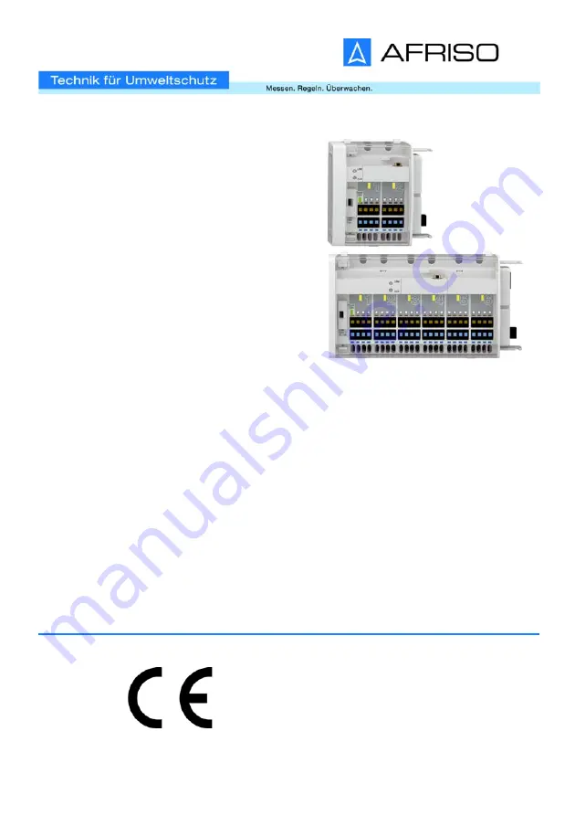
Typ: F2A
Typ: F6A

Summary of Contents for CosiTherm F2A

Page 1: ...4363 Güglingen Telefon 49 7135 102 0 Service 49 7135 102 211 Telefax 49 7135 102 147 info afriso com www afriso com Copyright 2021 AFRISO EURO INDEX GmbH Alle Rechte vorbehalten Betriebsanleitung Reglermodul Funk Produktfamilie CosiTherm Typ F2A Typ F6A ...

Page 2: ...sanleitung und alle zum Produkt gehörenden Unterlagen an alle Benutzer des Produkts weiter Wenn Sie der Meinung sind dass die Betriebsanleitung Fehler Wider sprüche oder Unklarheiten enthält wenden Sie sich vor Benutzung des Produkts an den Hersteller Diese Betriebsanleitung ist urheberrechtlich geschützt und darf ausschließ lich im rechtlich zulässigen Rahmen verwendet werden Änderungen vorbe hal...

Page 3: ...einer Gefährdungs situation werden Warnhinweise in unterschiedliche Gefahrenklassen unter teilt Zusätzlich werden in dieser Betriebsanleitung folgende Symbole verwendet GEFAHR GEFAHR macht auf eine unmittelbar gefährliche Situation aufmerksam die bei Nichtbeachtung unweigerlich einen schweren oder tödlichen Unfall zur Folge hat HINWEIS HINWEIS macht auf eine möglicherweise gefährliche Situation au...

Page 4: ...Ihnen vorgesehene Anwendung nach einem anerkannten Verfahren durch und treffen Sie entsprechend dem Ergebnis alle erforderlichen Sicher heitsmaßnahmen Berücksichtigen Sie dabei auch die möglichen Folgen eines Einbaus oder einer Integration des Produkts in ein System oder in eine Anlage Führen Sie bei der Verwendung des Produkts alle Arbeiten ausschließlich unter den in der Betriebsanleitung und au...

Page 5: ...n können Den Fachkräften müssen alle geltenden Bestimmungen Normen und Sicherheitsvorschriften die bei Arbeiten an und mit dem Produkt beachtet werden müssen bekannt sein 2 5 Persönliche Schutzausrüstung Verwenden Sie immer die erforderliche persönliche Schutzausrüstung Berücksichtigen Sie bei Arbeiten an und mit dem Produkt auch dass am Ein satzort Gefährdungen auftreten können die nicht direkt v...

Page 6: ...Sie sicher dass während des Transports und der Lagerung des Pro dukts die spezifizierten Umgebungsbedingungen eingehalten werden Benutzen Sie für den Transport die Originalverpackung Lagern Sie das Produkt nur in trockener sauberer Umgebung Stellen Sie sicher dass das Produkt bei Transport und Lagerung stoßge schützt ist Nichtbeachtung dieser Anweisungen kann zu Sachschäden führen ...

Page 7: ...eglermodul F6A C Abschlusskappe 1 Anlerntasten LRN Taste 2 Verriegelung 3 Betrieb Netzspannung LED grün 4 Thermischer Stellantrieb aktiv LED gelb 5 Funkmodul 6 Anschlussleiste für thermische Stellantriebe 7 Sicherungsfach 8 Reset Taste CLR Taste 4 4 5 4 2 7 6 2 7 4 3 2 1 A 5 2 3 1 6 C B 8 8 ...

Page 8: ...roduktbeschreibung DE F2A F6A 4 2 Abmessungen 4 3 Anwendungsbeispiel e Abbildung 1 Basismodul mit Reglermodul Uhrmodul Raumfühlern externer Antenne und Stellantrieben 95 mm 73 mm 182 mm 162 mm 24 mm 92 mm ...

Page 9: ...emperatur über EnOcean Funktelegramme direkt an das Produkt 4 5 Zulassungsdokumente Bescheinigungen Erklärungen Das Produkt entspricht EMV Richtlinie 2014 30 EU Niederspannungsrichtlinie 2014 35 EU Radio Equipment Directive RED 2014 53 EU Ökodesign Richtlinie 2009 125 EG RoHS Richtlinie 2011 65 EU 4 6 Technische Daten Parameter F2 F6 Allgemeine Daten Abmessungen B x H x T 73 x 92 x 45 mm 162 x 92 ...

Page 10: ... Schutzklasse EN 60730 1 II Schutzart EN 60529 IP 20 AFRISO empfiehlt die Verwendung von AFRISO Stellantrieben zur Sicher stellung der optimalen Systemleistung Wenn Stellantriebe anderer Her steller verwendet werden müssen folgende Grenzwerte eingehalten wer den Betriebsspannung AC 230 V 10 50 60 Hz max Betriebsstrom 9 mA max Einschaltstrom 140 mA 200 ms max Betriebsleistung 2 W Besonderes Merkmal...

Page 11: ...ntieren Stellen Sie sicher dass das Basismodul spannungsfrei ist 1 Öffnen Sie die Abdeckung mit Hilfe eines Schraubendrehers 2 Ziehen Sie die Abschlusskappe ab 3 Verbinden Sie das Produkt mit dem Basismodul und sichern bei des mit der Verriegelung ...

Page 12: ...12 Montage DE F2A F6A 4 Setzten Sie die Abschlusskappe auf das letzte Reglermodul 5 Hängen Sie die Abdeckung ein und schließen diese ...

Page 13: ...en GEFAHR ELEKTRISCHER SCHLAG DURCH SPANNUNGSFÜHRENDE TEILE Unterbrechen Sie vor Beginn der Arbeiten die Netzspannung und sichern Sie diese gegen Wiedereinschalten Stellen Sie sicher dass durch elektrisch leitfähige Gegenstände oder Medien keine Gefährdungen ausgehen können Nichtbeachtung dieser Anweisungen führt zu Tod oder schweren Verlet zungen Stellen Sie sicher dass das Anschluss konzept erst...

Page 14: ...n Sie das Kabel der Thermi schen Stellantriebe durch die Zugentlastung A und schließen Sie die Adern farbgleich an 2 Stecken Sie die abisolierten Adern bis zum Anschlag in die Klemme 3 Bei flexiblen Litzen oder zum Lösen der Klemmverbindung drü cken Sie den Lösehebel B A B ...

Page 15: ...emme anbringen 1 Fixieren Sie das Kabel auf der Rückseite des Produkts mit der Kabelklemme A Wenn Raum fühler mit Drahtanschluss einge setzt werden bringen Sie die Kabelklemme erst nach dem elek trischen Anschluss des Raumfüh ler an A A ...

Page 16: ...l angeschlossen sind 2 Verfahren Sie mit allen weiteren Kabeln gleich 3 Die Kabelklemmen können auch wieder gelöst werden Heben Sie die beiden Laschen B nach außen an und nehmen die Kabel klemme ab 1 Setzten Sie die Module Basis und Reglermodul mit den oberen Haken in die Hutschiene ein 2 Drücken Sie die Module Basis und Reglermodul unten in Rich tung Hutschiene bis sie hörbar einrasten B B ...

Page 17: ...E F2A F6A 5 4 Module von der Hutschiene abnehmen 1 Heben Sie die Module Basis und Reglermodul leicht an und nei gen Sie sie oben von der Hut schiene weg 2 Nehmen Sie die Module Basis und Reglermodul nach unten weg ...

Page 18: ...ADUNG Erden Sie sich immer bevor Sie die elektronischen Bauteile berühren Nichtbeachtung dieser Anweisungen kann zu Sachschäden führen 1 Öffnen Sie die Abdeckung des Produkts 2 Stecken Sie das Antennenkabel auf das Funkmodul und schrau ben Sie es fest 3 Schließen Sie die Abdeckung des Produkts wieder Klebeantenne anbringen siehe Seite 22 ...

Page 19: ...ass die Einzelraum Temperaturregelung in Betrieb ist und die Abdeckung des Produkts abgenommen ist Stellen Sie sicher dass die Raumfühler FT FTF mindestens einen Tag lang dem Tageslicht ausgesetzt waren oder dass sie über eine Bat terie verfügen Stellen Sie sicher dass sich die Raumfühler FT FTF in der Nähe des Produkts befinden Stellen Sie sicher dass die Rückseite jedes Raumfühlers FT FTF durchn...

Page 20: ... die gelbe LED des Produkts Regelkreis 1 für meh rere Sekunden Wenn innerhalb der nächsten 30 Sekunden die LRN Taste des Raumfühlers FT FTF erneut gedrückt wird wird der Raumfühler FT FTF wieder ausgelernt Wenn die gelbe LED für vier Sekunden erlischt war das Auslernen erfolg reich Nach dem erfolgreichen Einlernen oder Auslernen blinkt die gelbe LED am nächsten Regelkreis wieder im Sekundentakt 3 ...

Page 21: ... LED blinkt im Sekundentakt 30 Sekunden lang keine LRN Taste eines Raumfühlers FT FTF gedrückt wird wechselt das Produkt automatisch in den regulären Betriebsmodus 1 Drücken Sie die CLR Taste des Produkts mit der Spitze des Kugelschreibers solange min destens zwei Sekunden bis die gelbe LED Regelkreis 1 beginnt im Sekundentakt zu blinken Alle angelernten Raumfühler FT FTF dieses Produkts sind gelö...

Page 22: ...Positionieren Sie alle Raumfühler vorläufig in den Räumen in denen sie später montiert werden sollen 5 Drehen Sie alle Raumfühler auf die maximale Temperatur und warten Sie mindestens eine Minute Wenn der Empfang mit der Klebe Antenne im Verteilerschrank ausrei chend ist 1 Öffnen entfernen Sie die Abdeckung des Verteilerschranks Alle Regelkreise sind im Heizbetrieb Die gelben LEDs leuchten 2 Schli...

Page 23: ...es Verteilerschranks 2 Bohren Sie mit einer Bohrma schine ein Loch in die Innenseite des Verteilerschranks 3 Ziehen Sie das Kabel durch das gebohrte Loch 4 Stecken Sie denAntennenstecker auf das Anschluss Modul WL und schrauben Sie ihn fest 5 Entfernen Sie die Schutzfolie der Klebe Antenne und drücken Sie die Klebe Antenne am äußeren Rand des Verteilerschranks fest 6 Schließen Sie die Abdeckung de...

Page 24: ... Funktionsprüfung Raumfühler FT FTF Stellen Sie sicher dass die Raumtemperatur zwischen 15 C und 25 C liegt Prüfen Sie die Raumfühler FT FTF nacheinander 1 Stellen Sie sicher dass der zu prüfende Raumfühler mit dem korrekten Regelkreis verbunden ist 2 Stellen Sie den Raumfühler auf 30 C Nach einer Minute leuchtet die gelbe LED an dem Reglermodul auf mit dem der Raumfühler verbunden ist 3 Wiederhol...

Page 25: ...n Leuchtet Wenn Netzspannung für die Thermischen Stellantriebe vorhanden ist Erlischt Bei Ausfall der Netzspannung Bei Ausfall der Sicherung im Basismodul Bei Ausfall der Sicherung 1 B LED gelb Leuchtet Wenn der an diesen Regelkreis ange schlossene Raumfühler D FT FTF Hei zenergie oder Kühlung anfordert 1 A B A B 1 ...

Page 26: ...lten gesichert ist Problem Mögliche Ursache Fehlerbehebung Betrieb Netzspannung leuchtet nicht LED grün Keine Netzspannung Prüfen Sie die Span nungsversorgung Sicherung defekt Prüfen Sie die Siche rung Betrieb 5 V leuchtet nicht LED grün Keine Netzspannung Prüfen Sie die Span nungsversorgung Sicherung defekt Prüfen Sie die Siche rung Sonstige Störungen Netzteil defekt Bitte wenden Sie sich an die ...

Page 27: ...ng DE F2A F6A 2 Nehmen Sie den Sicherungshal ter heraus 3 Tauschen Sie die defekte Siche rung gegen einen G Sicherungs einsatz 5 x 20 mm 4 Setzen Sie den Sicherungshalter in das Sicherungsfach 5 Schließen Sie die Abdeckung ...

Page 28: ... werden 11 Rücksendung Vor einer Rücksendung Ihres Produkts müssen Sie sich mit uns in Verbin dung setzen 12 Gewährleistung Informationen zur Gewährleistung finden Sie in unseren Allgemeinen Geschäftsbedingungen im Internet unter www afriso com oder in Ihrem Kauf vertrag 1 Trennen Sie das Produkt von der Versorgungsspannung 2 Demontieren Sie das Produkt siehe Kapitel Montage in umgekehrter Reihenf...

Page 29: ...e und Zubehör Produkt HINWEIS UNGEEIGNETE TEILE Verwenden Sie nur Original Ersatz und Zubehörteile des Herstellers Nichtbeachtung dieser Anweisung kann zu Sachschäden führen Artikelbezeichnung Art Nr Abbildung Reglermodul F2A 78123 Reglermodul F6A 78124 ...

Page 30: ... und Zubehör DE F2A F6A Ersatzteile und Zubehör Artikelbezeichnung Art Nr Abbildung Thermischer Stellantrieb TSA 02 78882 Klebe Antenne 78175 Magnetfuß Antenne 78167 Antenne SMA Winkelste cker und Koaxialkabel 78168 ...

Page 31: ...ührende Informationen zu EnOcean Funksystemen Weiterführende Informationen zu Planung Installation und Betrieb von EnOcean Funksystemen finden Sie auf www enocean com Funkstandard Funktechnologie AN001 AN102 AN103 14 3 Möglichkeiten der EnOcean Technologie Unterlagen über EnOcean Technologien finden Sie im Internet unter www afrisohome com Auf unserem YouTube Channel finden Sie eine Reihe von Vide...

Page 32: ...32 Informationen zu EnOcean Funk DE F2A F6A ...

Page 33: ...glingen Telefon 49 7135 102 0 Service 49 7135 102 211 Telefax 49 7135 102 147 info afriso com www afriso com Copyright 2020 AFRISO EURO INDEX GmbH All rights reserved Operating instructions Controller module wireless Product family CosiTherm Type F2A Type F6A ...

Page 34: ...as well as all other product related doc uments on to all owners of the product If you feel that these operating instructions contain errors inconsisten cies ambiguities or other issues contact the manufacturer prior to using the product These operating instructions are protected by copyright and may only be used as provided for by the corresponding copyright legislation We reserve the right to mo...

Page 35: ... highlighted with warning symbols and warning words Depending on the severity of a hazard the safety messages are classified according to different hazard categories In addition the following symbols are used in these operating instructions DANGER DANGER indicates a hazardous situation which if not avoided will result in death or serious injury NOTICE NOTICE indicates a hazardous situation which i...

Page 36: ... addition perform a risk assessment in view of the planned application according to an approved risk assessment method and implement the appropriate safety measures based on the results of the risk assessment Take into account the consequences of installing or integrating the product into a system or a plant When using the product perform all work and all other activities in conjunc tion with the ...

Page 37: ...rsons working on and with the product must be fully familiar with all directives standards and safety regulations that must be observed for per forming such work 2 5 Personal protective equipment Always wear the required personal protective equipment When performing work on and with the product take into account that hazards may be present at the installation site which do not directly result from...

Page 38: ...ify compliance with the specified ambient conditions during transport or storage of the product Use the original packaging when transporting the product Store the product in a clean and dry environment Verify that the product is protected against shocks and impact during trans port and storage Failure to follow these instructions can result in equipment damage ...

Page 39: ...Controller module F6A C End cover 1 Teach in key LRN key 2 Catch 3 Operation mains voltage LED green 4 Thermostatic actuator active LED yellow 5 Wireless module 6 Terminal block for thermostatic actuators 7 Fuse compartment 8 Reset button CLR button 4 4 5 4 2 7 6 2 7 4 3 2 1 A 5 2 3 1 6 C B 8 8 ...

Page 40: ...description EN F2A F6A 4 2 Dimensions 4 3 Application example s Fig 1 Base module with controller module timer module room temperature sensors external antenna and actuators 95 mm 73 mm 182 mm 162 mm 24 mm 92 mm ...

Page 41: ...ignals of the room temperature sensors and the base mod ule Multiple products with 2 or 6 control circuits can be installed adjacent to each other The room sensors FT FTF transmit the actual temperature and the refer ence temperature directly to the product via wireless EnOcean telegrams 4 5 Approvals conformities certifications The product complies with EMC Directive 2014 30 EU Low Voltage Direct...

Page 42: ...a tors T 1 A T 3 15 A Permissible cable type to thermostatic actuators H03 VV H2 F 2 x 0 75 mm The following components may be connected to one product Room temperature sensor Max 2 Max 6 Thermostatic actuators Per control circuit up to 4 AFRISO TSA Electrical safety Protection class II EN 60730 1 Degree of protection IP 20 EN 60529 Electromagnetic compatibility EMC Emitted interference immu nity ...

Page 43: ...from other manufacturers are used the fol lowing limit values must be met Operating voltage AC 230 V 10 50 60 Hz Ma operating current 9 mA Max inrush current 140 mA 200 ms Max operating power 2 W Special characteristic Short circuit proof protected against overvoltage Actuators of other manufac turers connected per control circuit Max 2 ...

Page 44: ...A 5 Mounting 5 1 Mounting the product Verify that the base module is disconnected from mains 1 Open the cover using a screw driver 2 Pull off the end cover 3 Connect the product to the base module and secure with the catch ...

Page 45: ...13 Mounting EN F2A F6A 4 Refit the end cover onto the last controller module 5 Refit the cover and close it ...

Page 46: ...sult in death or serious injury DANGER ELECTRIC SHOCK CAUSED BY LIVE PARTS Disconnect the mains voltage supply before performing the work and ensure that it cannot be switched on Verify that no hazards can be caused by electrically conductive objects or media Failure to follow these instructions will result in death or serious injury Verify that a connec tion concept has been created Verify that a...

Page 47: ... cables of the thermo static actuators through the strain reliefs A and connect the wires to the corresponding terminals observe colour coding 2 Push the stripped wires all the way into the terminals 3 In the case of flexible wires or for disconnecting wires push the catch B A B ...

Page 48: ... cable clamp 1 Fix the cable at the rear of the product using the cable clamp B If room temperature sensors with a wired connection are used first make the electrical connection of the room temperature sensors and then fit the cable clamp A A ...

Page 49: ...e connected 2 Repeat this procedure for all other cables 3 It is possible to open the cable clamps To do so pull the two tabs B outwards and remove the cable clamp 1 Fit the modules base module and controller module onto the DIN rail with the upper clamps 2 Push the lower end of the mod ules base module and controller module towards the DIN rail until they snap in with a click B B ...

Page 50: ... F6A 5 4 Removing modules from a DIN rail 1 Slightly lift the modules base module and controller modules and tilt the top away from the DIN rail 2 Remove the modules base mod ule and controller modules towards the bottom ...

Page 51: ...IC DISCHARGE Always earth yourself before touching electronic components Failure to follow these instructions can result in equipment damage 1 Open the cover of the product 2 Push the antenna cable onto the wireless module and screw it on 3 Close the cover of the product See Page 23 for information on mounting the adhesive antenna ...

Page 52: ...rify that the single room temperature controller is in operation and that the cover of the product has been removed Verify that the room temperature sensors FT FTF have been exposed to sunlight for at least one day or that they have a battery Verify that the wireless room sensors FT FTF are close to the prod uct Verify that the rear side of each of the room temperature sensors FT FTF are numbered ...

Page 53: ... 1 of the product lights up for several seconds If you press the LRN key of the room temperature sensor FT FTF again within the next 30 seconds the teach in process is revoked and the room temperature sensor FT FTF is disconnected If the yellow LED if off for four seconds revocation of the teach in process was successful After successful teach in or revoca tion of teach in the yellow LED flashes a...

Page 54: ...sensor FT FTF in LRN mode the yellow control cir cuit LED flashes at intervals of one second for a period of 30 seconds the product automatically switches back to normal operating mode 1 Press the CLR key of the product with the tip of the ballpoint pen for at least two seconds until the yel low LED for control circuit 1 starts flashing All taught in room temperature sensors FT FTF of this prod uc...

Page 55: ... the room temperature sensors in the rooms in which you will ultimately install them 5 Set all room temperature sensors to maximum temperature and wait for at least one minute If the reception is sufficient with the adhesive antenna in the cabinet 1 Open remove the cover of the cabinet All control circuits are in heating mode The yellow LEDs light 2 Close the cover of the cabinet 3 Set all room te...

Page 56: ...n remove the cover of the cabinet 2 Drill a hole into the inside of the cabinet using a power drill 3 Route the cable through the drilled hole 4 Push the antenna connector onto the connection module WL and screw it on 5 Remove the protective film from the adhesive antenna and push the adhesive antenna onto the outer edge of the cabinet 6 Close the cover of the cabinet ...

Page 57: ...oom temperature sensor FT FTF Verify that the room temperature is between 15 C and 25 C Test the room temperature sensors FT FTF one after another 1 Verify that the room temperature sensor to be tested is connected to the correct control circuit 2 Set the room temperature sensor to 30 C After one minute the yellow LED lights up at the controller module to which the room temperature sensor is conne...

Page 58: ... green Solid lit When mains voltage for the thermostatic actuators is applied Goes off In the case of power outage If the fuse in the base module trips If the fuse 1 trips B LED yellow Solid lit When the room temperature sensor D FT FTF connected to this control circuit is requesting heating energy or cooling 1 A B A B 1 ...

Page 59: ...oltage is interrupted and cannot be switched on Problem Possible reason Repair LED operation mains voltage not lit green LED No mains voltage Check the supply volt age Fuse tripped Check the fuse LED 5 V operation not lit green LED No mains voltage Check the supply volt age Fuse tripped Check the fuse Other malfunctions Power supply unit defec tive Contact the AFRISO service hotline 1 Open the cov...

Page 60: ...28 Troubleshooting EN F2A F6A 2 Remove the fuse holder 3 Replace the defective fuse with a G fuse insert 5 x 20 mm 4 Insert the fuse holder into the fuse compartment 5 Close the cover ...

Page 61: ...nts must not be disposed of together with the normal household waste 11 Returning the device Get in touch with us before returning your product 12 Warranty See our terms and conditions at www afriso com or your purchase contract for information on warranty 1 Disconnect the product from mains 2 Dismount the product see chapter Mounting reverse sequence of steps 3 Dispose of the product ...

Page 62: ...ries Product NOTICE UNSUITABLE PARTS Only use genuine spare parts and accessories provided by the manufac turer Failure to follow these instructions can result in equipment damage Product designation Part no Figure Controller module F2A 78123 Controller module F6A 78124 ...

Page 63: ...essories EN F2A F6A Spare parts and accessories Product designation Part no Figure Thermostatic actuator TSA 02 78882 Adhesive antenna 78175 Magnetic foot antenna 78167 Antenna angular SMA con nector and coaxial cable 78168 ...

Page 64: ...information on EnOcean wireless systems Additional information on planning installation and operation of EnOcean wireless systems can be found at www enocean com Wireless standard Wireless technology AN001 AN102 AN103 14 3 Features of the EnOcean technology Visit www afrisohome de for documents on EnOcean technologies A variety of videos on AFRISO products can also be found on the AFRISO YouTube c...

Page 65: ... Téléphone 49 7135 102 0 Service clientèle 49 7135 102 211 Téléfax 49 7135 102 147 info afriso com www afriso com Copyright 2021 AFRISO EURO INDEX GmbH Tous droits réservés Notice technique Module de régulation sans fil Famille de produit CosiTherm Type F2A Type F6A ...

Page 66: ...ique et toute la documentation relative au pro duit à tous les utilisateurs du produit Si vous êtes d avis que la notice technique contient des erreurs des contradictions ou des ambiguïtés adressez vous au fabricant avant d uti liser le produit Cette notice technique est protégée au titre de la propriété intellectuelle elle doit être utilisée exclusivement dans le cadre autorisé par la loi Sous ré...

Page 67: ... de mise en garde et de mots d avertissement En fonction de la gravité du risque les consignes de sécurité sont réparties dans diffé rentes classes de risques Les symboles suivants sont également utilisés dans cette notice technique DANGER DANGER signale une situation directement dangereuse qui si elle n est pas évitée entraîne la mort ou des blessures graves AVIS AVIS signale une situation potent...

Page 68: ...nnu et prenez toutes les mesures de sécurité nécessaires correspondant au résultat Prenez aussi en compte les conséquences possibles du montage ou de l intégration du produit dans un système ou une installation Pendant l utilisation du produit effectuez toutes les opérations exclusivement dans les conditions spécifiées dans cette notice technique et sur la plaque signalétique conformément aux donn...

Page 69: ...n du produit Tous les règlements normes et consignes de sécurité en vigueur sur le lieu d installation doivent être connus du personnel qualifié travaillant sur le pro duit et avec celui ci 2 5 Équipement de protection individuelle Utilisez toujours l équipement de protection individuel requis En travaillant sur le produit et avec celui ci tenez compte des dangers susceptibles de se présenter sur ...

Page 70: ...RIÉE Assurez vous que les conditions ambiantes spécifiées sont respectées pen dant le transport et le stockage Utilisez l emballage d origine pour le transport Stockez le produit dans un lieu sec et propre Assurez vous que le produit est à l abri des chocs pendant le transport et le stockage La non observation de ces instructions peut causer des dommages maté riels ...

Page 71: ...e de régulation F6A C Bouchon 1 Touches LRN 2 Verrouillage 3 Fonctionnement tension secteur LED verte 4 Actionneur thermique actif LED jaune 5 Module sans fil 6 Bloc de raccordement pour les actionneurs thermiques 7 Compartiment fusible 8 Touche Reset touche CLR 4 4 5 4 2 7 6 2 7 4 3 2 1 A 5 2 3 1 6 C B 8 8 ...

Page 72: ...u produit FR F2A F6A 4 2 Dimensions 4 3 Exemple s d application Figure 1 Module de base avec module de régulation module d horloge sonde d ambiances antenne externe et actionneurs 95 mm 73 mm 182 mm 162 mm 24 mm 92 mm ...

Page 73: ...chacun Les sondes d ambiance FT FTF transmettent la température réelle et la température de consigne vers le produit par l intermédiaire des télégrammes EnOcean 4 5 Agréments certificats déclarations Le produit est conforme à Directive CEM 2014 30 UE Directive basse tension 2014 35 UE Radio Equipment Directive RED 2014 53 UE Directive écoconception 2009 125 CE Directive RoHS 2011 65 UE 4 6 Caracté...

Page 74: ...r circuit de commande 4AFRISO TSA max Données électriques Classe de protection EN 60730 1 II Degré de protection EN 60529 IP 20 AFRISO recommande l utilisation d actionneurs AFRISO afin d assurer les performances optimales du système Si des actionneurs d autres fabricants sont utilisés les valeurs limites suivantes doivent être respectées Tension de service AC 230 V 10 50 60 Hz courant de service ...

Page 75: ...e 5 1 Montage du produit Assurez vous que le module de base n est pas sous tension 1 Démontez le couvercle à l aide d un tournevis 2 Retirez le bouchon 3 Connectez le produit au module de base et fixez les deux avec le verrouillage ...

Page 76: ...12 Montage FR F2A F6A 4 Mettez le bouchon sur le dernier module de régulation 5 Mettez le couvercle en place et fermez le ...

Page 77: ...graves DANGER CHOC ÉLECTRIQUE PROVOQUÉ PAR LES PARTIES SOUS TENSION Coupez la tension secteur avant d effectuer les travaux et prenez toutes les mesures nécessaires pour éviter la remise en marche Assurez vous que des objets conducteurs ou des fluides conducteurs ne causent aucun risque La non observation de ces instructions entraîne la mort ou des blessures graves Assurez vous qu un concept de ra...

Page 78: ...e câble des Action neurs Thermiques par le dispositif de décharge de traction et connectez les fils aux bornes cor respondantes observer le codage couleur 2 Poussez les fils dénudés dans les bornes 3 Dans le cas des fils souples ou pour déconnecter les fils appuyez sur le loquet B A B ...

Page 79: ...e câble 1 Fixez le câble à l arrière du module du produit à l aide du serre câble A Si des sondes d ambiance avec une connexion filaire sont utilisés établissez d abord la connexion électrique des sondes d ambiance puis montez le serre câble A A ...

Page 80: ...tez cette procédure pour tous les autres câbles 3 Il est possible de retirer les serre câbles Pour ce faire tirez les deux languettes B vers l exté rieur et retirez le serre câble 1 Positionnez les modules module de base et module de régulation dans le rail DIN par les crochets du haut 2 Appuyez sur le bas des modules module de base et module de régulation en direction du rail DIN jusqu à ce que l...

Page 81: ...er les modules du rail DIN 1 Soulevez légèrement les modules module de base et module de régulation et inclinez le haut des modules pour les dégager du rail DIN 2 Retirez les modules module de base et module de régulation vers le bas ...

Page 82: ...avant de toucher des composants susceptibles d être endommagés par décharge électrostatique La non observation de ces instructions peut causer des dommages maté riels 1 Ouvrez le couvercle du produit 2 Poussez le câble de l antenne sur le module sans fil et vissez le 3 Refermez le couvercle du produit Voir Page 22 pour des informations sur le montage de l antenne adhé sive ...

Page 83: ...n Assurez vous que le système de régulation de température pièce par pièce est en marche et le couvercle démonté Assurez vous que les sondes d ambiance ont été exposées à la lumière du soleil pendant une journée au moins ou qu ils ont une pile Assurez vous que les sondes d ambiance sont à proximité du produit Vérifiez que le côté arrière de chaque sonde d ambiance soit numérotée consécutivement et...

Page 84: ...endant plusieurs secondes pour indiquer la réussite du teach in Si vous appuyez sur la touche LRN de la sonde d ambiance FT FTF à nouveau dans les 30 secondes le teach in de la sonde d ambiance FT FTF est inversé Si la LED jaune s éteint pendant quatre secondes le teach in a été inversé Après que le teach in ou l inversion du teach in est terminé la LED jaune clignote à nouveau à intervalles d une...

Page 85: ...n mode LRN la LED jaune du circuit de commande clignote à inter valles d une seconde pour une durée de 30 secondes le produit revient en mode de fonctionnement normal 1 Appuyez sur la touche CLR du produit avec la pointe du stylo à bille pendant au moins deux secondes jusqu à ce que la LED jaune pour le circuit de commande 1 se met à clignoter à intervalles d une seconde Cette opération supprime t...

Page 86: ...sondes d ambiance dans les pièces dans lesquelles elles seront installées ultérieurement 5 Réglez toutes les sondes d ambiance sur la température maximale et attendez au moins une minute Si la réception avec l antenne adhésive dans l armoire de distribution est suffisante 1 Ouvrez retirez le couvercle de l armoire de distribution de distribution Tous les circuits de commande sont en mode chauffage...

Page 87: ...armoire de distribution de distri bution 2 Percez un trou à l intérieur de l armoire de distribution à l aide d une perceuse 3 Faites passer le câble à travers le trou percé 4 Poussez le connecteur de l antenne sur le module de connexion WL et vissez le 5 Retirez le film protecteur de l antenne adhésive et appuyez l antenne adhésive sur le bord extérieur de l armoire de distribu tion 6 Fermez le c...

Page 88: ...ionnement Sonde d ambiance FT FTF Vérifiez que la température ambiante est comprise entre 15 C et 25 C Vérifiez les sondes d ambiance FT FTF l une après l autre 1 Vérifiez que la sonde d ambiance à vérifier est connecté au circuit de com mande correct 2 Réglez la sonde d ambiance sur 30 C Après d une minute la LED jaune s allume sur le module de régulation auquel la sonde d ambiance est reliée 3 R...

Page 89: ...Allumé En présence de tension secteur pour les Actionneurs Thermiques S éteint En cas de panne de secteur Si le fusible dans le module de base déclenche Si le fusible 1 déclenche B LED jaune Allumé Si la sonde d ambiance D FT FTF reliée à ce circuit de commande demande d éner gie de chauffage ou refroidissement 1 A B A B 1 ...

Page 90: ...nécessaires pour éviter la remise en marche Problème Cause possible Action corrective La LED verte tension secteur ne s allume pas Pas de tension secteur Vérifiez l alimentation Fusible défectueux Vérifiez le fusible La LED verte de fonc tionnement 5 V ne s allume pas Pas de tension secteur Vérifiez l alimentation Fusible défectueux Vérifiez le fusible Autre dérangement Bloc d alimentation défectu...

Page 91: ...ssion des dérangements FR F2A F6A 2 Retirez le porte fusible 3 Remplacez le fusible défectueux par un fusible type insert G 5 x 20 mm 4 Insérez le porte fusible dans le compartiment fusible 5 Fermez le couvercle ...

Page 92: ... éliminés avec les ordures ménagères 11 Retour Avant de retourner le produit il faut que vous preniez contact avec nous 12 Garantie Les informations sur la garantie figurent dans nos Conditions générales de vente sur le site www afriso com ou dans votre contrat d achat 1 Débranchez le produit de la tension d alimentation 2 Démontez le produit voir chapitre Montage effectuez les opérations en ordre...

Page 93: ... AVIS PIÈCES INADAPTÉES N utilisez que des accessoires et des pièces détachées d origine provenant du fabricant La non observation de ces instructions peut causer des dommages maté riels Désignation de l article Référence Figure Module de régulation F2A 78123 Module de régulation F6A 78124 ...

Page 94: ...ssoires FR F2A F6A Pièces détachées et accessoires Désignation de l article Référence Figure Actionneur thermique TSA 02 78882 Antenne adhésive 78175 Antenne à pied magnétique 78167 Antenne fiche coudée SMA et câble coaxial 78168 ...

Page 95: ...sans fil EnO cean Vous trouverez des informations supplémentaires sur la planification l instal lation et l exploitation de systèmes sans fil EnOcean sur www eno cean com Standard de communication radio Technologie de communication radio AN001 AN102 AN103 14 3 Possibilités de la technologie EnOcean Vous trouverez des documents supplémentaires sur les technologies EnO cean sur www afrisohome com Vi...

Page 96: ...32 Informations sur EnOcean sans fil FR F2A F6A ...

Page 97: ...lingen telefon 49 7135 102 0 servis 49 7135 102 211 telefaks 49 7135 102 147 info afriso com www afriso com Copyright 2020 AFRISO EURO INDEX GmbH Wszelkie prawa zastrzeżone Instrukcja eksploatacji Moduł sterujący bezprzewodowy System CosiTherm Typ F2A Typ F6A ...

Page 98: ...z z jego pomocą Należy przekazać instrukcję eksploatacji oraz wszystkie dokumenty nale żące do produktu wszystkim użytkownikom produktu W razie wystąpienia opinii że instrukcja eksploatacji zawiera błędy sprzecz ności lub niejasności należy skontaktować się z producentem przed odda niem produktu do użytkowania Niniejsza instrukcja eksploatacji jest chroniona prawem autorskim wobec czego wolno ją s...

Page 99: ...lasy zagrożenia w zależności od stopnia ciężkości sytuacji zagrożenia W niniejszej instrukcji eksploatacji stosowane są dodatkowo następujące sym bole NIEBEZPIECZEŃSTWO NIEBEZPIECZEŃSTWO zwraca uwagę na bezpośrednio występującą niebez pieczną sytuację która w przypadku nieprzestrzegania spowoduje niechybnie ciężki lub śmiertelny wypadek WSKAZÓWKA WSKAZÓWKA zwraca uwagę na ewentualnie niebezpieczną...

Page 100: ...y ocenę ryzyka w odniesieniu do konkretnego zastosowania przewidzianego przez użytkownika oraz podjąć wszelkie odpowiednie działania na rzecz bezpieczeństwa zgodnie z wynikiem procedury oceny ryzyka Należy też przy tym uwzględnić możliwe konsekwencje wynikające z zabudowy lub integracji produktu w systemie lub instalacji Podczas użytkowania produktu wszystkie prace należy przeprowadzać wyłącznie w...

Page 101: ...acownikom wykwalifikowanym muszą być znane wszystkie obowiązujące warunki normy i przepisy bezpieczeństwa których należy przestrzegać pod czas czynności wykonywanych przy produkcie oraz z jego pomocą 2 5 Osobiste wyposażenie ochronne Należy zawsze stosować wymagane osobiste wyposażenie ochronne Pod czas czynności wykonywanych przy produkcie oraz z jego pomocą należy także uwzględnić że w miejscu u...

Page 102: ...u i składowania produktu dotrzymy wane są warunki otoczenia wyszczególnione w specyfikacji Do celów transportowych należy wykorzystywać oryginalne opakowanie Produkt należy przechowywać wyłącznie w suchym i czystym otoczeniu Należy upewnić się że podczas transportu i składowania produkt jest chro niony przed uderzeniami Nieprzestrzeganie niniejszych zaleceń może doprowadzić do powstania szkód mate...

Page 103: ...rzyciski programowania przycisk LRN 2 zatrzask 3 włączone napięcie sieciowe zie lona dioda LED 4 siłownik termoelektryczny włą czony żółta dioda LED 5 moduł bezprzewodowy 6 listwa przyłączeniowa do siłowni ków termoelektrycznych 7 komora bezpiecznika 8 przycisk reset przycisk CLR 4 4 5 4 2 7 6 2 7 4 3 2 1 A 5 2 3 1 6 C B 8 8 ...

Page 104: ...tu PL F2A F6A 4 2 Wymiary 4 3 Przykład y zastosowania Ilustracja 1 Moduł podstawowy z modułem sterującym modułem czasowym czujni kami pokojowymi anteną zewnętrzną i siłownikami 95 mm 73 mm 182 mm 162 mm 24 mm 92 mm ...

Page 105: ...wartość rzeczywistą oraz wartość zadaną temperatury za pośrednictwem sygnałów wysyłanych w technologii bezprzewodowej według protokołu EnO cean bezpośrednio do produktu 4 5 Dopuszczenia certyfikaty deklaracje Produkt jest zgodny z dyrektywą unijną dotyczącą kompatybilności elektromagnetycznej 2014 30 UE dyrektywą unijną dotyczącą sprzętu elektrycznego przewidzianego do sto sowania w określonych gr...

Page 106: ... bez kondensacji Zasilanie elektryczne napięcie znamionowe przez moduł podstawowy AC 230 V DC 5 V moc nominalna tylko moduł sterujący 0 3 W 0 5 W bezpiecznik siłowników ter moelektrycznych T 1 A T 3 15 A typ przewodów do stosowa nia z siłownikami termoelek trycznymi H03 VV H2 F 2 x 0 75 mm Do produktu można podłączyć następujący osprzęt czujniki pokojowe maksymalnie 2 maksymalnie 6 siłowniki termo...

Page 107: ...1 A2 2013 EN 62479 2010 AFRISO zaleca stosowanie siłowników AFRISO w celu zabezpieczenia opty malnej wydajności pracy systemu W przypadku stosowania siłowników innych producentów trzeba dotrzymywać następujących wartości granicz nych napięcie robocze AC 230 V 10 50 60 Hz maksymalny prąd roboczy 9 mA maksymalny prąd włącze niowy 140 mA 200 ms maksymalna moc robocza 2 W cecha szczególna odporne na z...

Page 108: ...ontaż produktu Należy upewnić się że moduł podstawowy nie znajduje się pod napięciem 1 Otworzyć osłonę za pomocą śru bokręta 2 Zdjąć pokrywkę zamykającą 3 Połączyć produkt z modułem pod stawowym i zabezpieczyć zatrza skiem oba urządzenia ...

Page 109: ...mocować i zamknąć osłonę NIEBEZPIECZEŃSTWO PORAŻENIE PRĄDEM ELEKTRYCZNYM Należy upewnić się że rodzaj instalacji elektrycznej nie zmniejsza zakresu ochrony przed porażeniem prądem elektrycznym klasa ochronności izolacja ochronna Nieprzestrzeganie niniejszych zaleceń prowadzi do śmierci lub poważ nych obrażeń ...

Page 110: ...czeniem napięcia Należy upewnić się że przedmioty lub media przewodzące energię elektryczną nie stanowią zagrożenia Nieprzestrzeganie niniejszych zaleceń prowadzi do śmierci lub poważ nych obrażeń Należy upewnić się że została sporzą dzona koncepcja wykonania przyłączy Należy upewnić się że żadne przewody nie znajdują się pod napięciem 1 Należy usunąć izola cję przewodów w sposób przedsta wiony na...

Page 111: ...iłowni ków termoelektrycznych przez uchwyt odciążający A zabezpie czający przed zerwaniem i podłą czyć żyły zgodnie z kolorami 2 Żyły z usuniętą izolacją wsunąć do zacisku do oporu 3 W przypadku elastycznych prze wodów licowych lub w celu polu zowania złącza zaciskowego wci snąć dźwigienkę B A B ...

Page 112: ...cowanie opaski na przewodzie 1 Przymocować przewód po tylnej stronie produktu za pomocą opa ski A W razie stosowania prze wodowych czujników pokojowych opaskę zamocować dopiero po wykonaniu podłączenia elektrycz nego czujników A A ...

Page 113: ...szystkie przewody są podłączone 2 Powtórzyć czynność dla wszyst kich przewodów 3 Opaski dają się ponownie zde montować W tym celu podważyć oba piórka B w kierunku zewnętrznym i zdjąć opaskę 1 Górne haczyki modułów moduł podstawowy i moduł sterujący zamocować w szynie montażowej DIN 2 Docisnąć dolną część modułów moduł podstawowy i moduł steru jący w kierunku szyny aż do momentu słyszalnego zabloko...

Page 114: ...montaż modułów z szyny montażowej DIN 1 Lekko unieść moduły moduł pod stawowy i moduł sterujący i odchylić ich górną część od szyny montażowej DIN 2 Zdjąć moduły moduł podstawowy i moduł sterujący pociągając je w kierunku dolnym ...

Page 115: ...nięciem elektronicznych elementów układu zawsze konieczne jest wcześniejsze uziemienie osoby wykonującej obsługę Nieprzestrzeganie niniejszych zaleceń może doprowadzić do powstania szkód materialnych 1 Otworzyć osłonę produktu 2 Nasadzić przewód anteny na moduł bezprzewodowy i mocno go przykręcić 3 Ponownie zamknąć osłonę pro duktu Zamocować antenę klejoną patrz Strona 23 ...

Page 116: ...ię że regulator temperatury pokojowej znajduje się w trybie pracy a osłona produktu została zdemontowana Należy upewnić się że czujniki pokojowe FT FTF były poddane działa niu światła dziennego przez okres co najmniej jednego dnia lub że są wyposażone w baterię Należy upewnić się że czujniki pokojowe FT FTF są umieszczone w pobliżu produktu Należy upewnić się że tylna strona każdego czujnika pokoj...

Page 117: ...kilka sekund Jeśli w ciągu kolejnych 30 sekund przycisk LRN czujnika pokojowego FT FTF zostanie znów wciśnięty zaprogramowanie czujnika pokojo wego FT FTF zostanie ponownie wykasowane Wygaśnięcie zółtej diody LED na okres czterech sekund oznacza że zaprogramowanie czuj nika zostało prawidłowo wykasowane Po prawidłowym zaprogramowaniu lub wykasowaniu zaprogramowania żółta dioda LED następnego obwod...

Page 118: ... w takcie sekundowym żaden przycisk LRN czujnika pokojowego FT FTF nie zostanie wciśnięty przez okres 30 sekund produkt przełączy się auto matycznie na regularny tryb pracy 1 Ostrym końcem długopisu wciskać przycisk CLR produktu tak długo przez okres co najmniej dwóch sekund aż żółta dioda LED obwodu regulacji 1 zacznie migać w takcie sekundowym Zaprogramowanie wszystkich czujników pokojowych FT F...

Page 119: ...jniki pokojowe należy rozmieścić tymczasowo w tych pomieszczeniach w których mają później zostać zamontowane 5 Ustawić wszystkie czujniki pokojowe na maksymalną temperaturę i odczekać co najmniej jedną minutę Jeśli odbiór sygnału przy pomocy anteny klejonej umieszczonej w szafce rozdzielczej jest dostateczny 1 Otworzyć usunąć osłonę szafki rozdzielczej Wszystkie obwody regulacji znajdują się w try...

Page 120: ...j 1 Otworzyć usunąć osłonę szafki rozdzielczej 2 Przy pomocy wiertarki przewiercić otwór do wnętrza szafki rozdziel czej 3 Przeciągnąć przewód przez prze wiercony otwór 4 Nasadzić wtyczkę anteny na moduł przyłączeniowy WL i mocno ją przykręcić 5 Z anteny klejonej usunąć folię ochronną i docisnąć mocno antenę do zewnętrznej krawędzi szafki rozdzielczej 6 Zamknąć osłonę szafki rozdziel czej ...

Page 121: ...a Czujniki pokojowe FT FTF Należy upewnić się że temperatura w pomieszczeniu utrzymuje się w gra nicach od 15 C do 25 C Kolejno skontrolować czujniki pokojowe FT FTF 1 Należy upewnić się że kontrolowany czujnik pokojowy jest połączony z pra widłowym obwodem regulacji 2 Czujnik pokojowy ustawić na pozycji 30 C Po jednej minucie żółta dioda LED zaczyna się świecić na tym module ste rującym z którym ...

Page 122: ...ięcie sieciowe jest podłączone do siłowników termoelektrycznych gaśnie w razie zaniku napięcia sieciowego w razie uszkodzenia bezpiecznika w module podstawowym w razie uszkodzenia bezpiecznika 1 B żółta dioda LED świeci się jeśli czujnik pokojowy D FT FTF podłą czony do tego obwodu regulacji wysyła zapotrzebowanie na energię grzewczą lub chłodzącą 1 A B A B 1 ...

Page 123: ...zyczyna Usunięcie usterki sygnalizacja włączo nego napięcia siecio wego nie świeci się zie lona dioda LED brak napięcia siecio wego sprawdzić układ zasila nia uszkodzony bezpiecznik sprawdzić bezpiecznik sygnalizacja włączo nego napięcia 5 V nie świeci się zielona dioda LED brak napięcia siecio wego sprawdzić układ zasila nia uszkodzony bezpiecznik sprawdzić bezpiecznik pozostałe zakłócenia uszkod...

Page 124: ...usterek PL F2A F6A 2 Wyjąć uchwyt bezpiecznika 3 Wymienić uszkodzony bezpiecznik na zabezpieczający urządzenie wkład bezpiecznikowy 5 x 20 mm 4 Zamontować uchwyt bezpiecznika w komorze bezpiecznika 5 Zamknąć osłonę ...

Page 125: ... nie wolno utylizować wraz z odpadami z gospo darstw domowych 11 Zwrot Przed zwrotną wysyłką produktu wymagany jest kontakt z producentem 12 Gwarancja Informacje dotyczące gwarancji są dostępne w naszych Ogólnych Warunkach Handlowych w internecie pod adresem www afriso com lub w umowie kupna 1 Odłączyć produkt od napięcia 2 Wykonać demontaż produktu patrz rozdział Montaż w odwrotnej kolejności 3 P...

Page 126: ...ukt WSKAZÓWKA NIEWŁAŚCIWE CZĘŚCI Należy stosować wyłącznie oryginalne części zamienne i wyposażenie dodat kowe producenta Nieprzestrzeganie niniejszego zalecenia może doprowadzić do powstania szkód materialnych Nazwa artykułu Numer artykułu Ilustracja moduł sterujący F2A 78123 moduł sterujący F6A 78124 ...

Page 127: ...e PL F2A F6A Części zamienne i wyposażenie dodatkowe Nazwa artykułu Numer artykułu Ilustracja siłownik termoelektryczny TSA 02 78882 antena klejona 78175 antena z podstawką magnetyczną 78167 antena złącze kątowe SMA i kabel koncentryczny 78168 ...

Page 128: ...ych EnOcean Więcej informacji o planowaniu instalowaniu i eksploatacji systemów bezprze wodowych EnOcean zawiera strona internetowa www enocean com Standard bezprzewodowy technologia bezprzewodowa AN001 AN102 AN103 14 3 Możliwości technologii EnOcean Informacje o zastosowaniach technologicznych systemu EnOcean znajdują się w internecie na stronie www afrisohome de Zestaw filmów wideo na temat prod...

Reviews: