


6
ROGUE
®
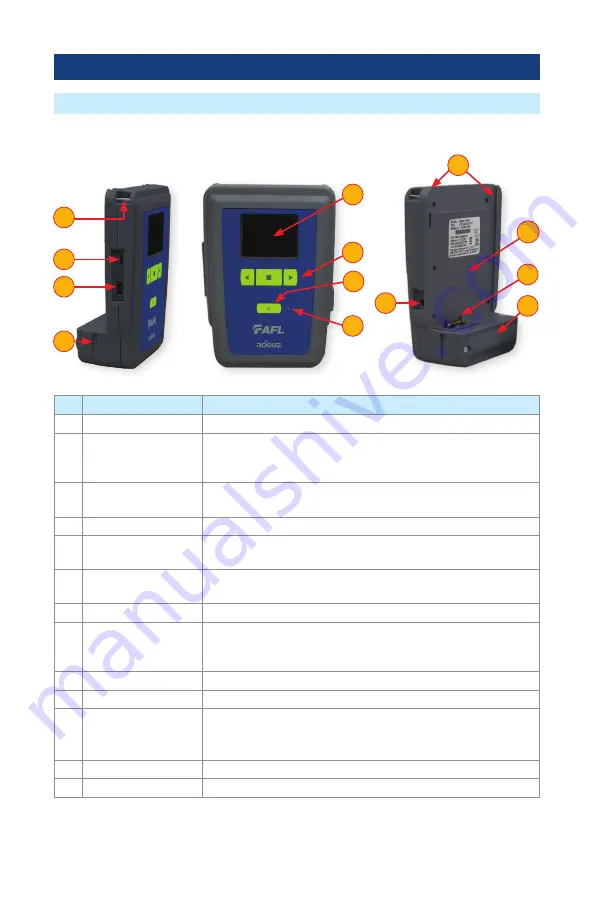
cB1 Overview
Hardware Overview
Ref Feature
Description
1 Strap Eyelet
Used to attach an adjustable carry strap supplied with your cB1 .
2 Mini-USB Function
Port
This port may be used to connect the cB1 to a PC for downloading
and managing test data, updating User Interface software or for
remote control of the device .
3 USB Host Port
This USB port allows connection to USB devices (keyboard, USB
flash drive, or other USB devices)
4 Key Slot
Used to mount a Kickstand accessory on the ROGUE cB1 .
5 Touch Screen Display
Contains on-screen controls and menus, allowing the user to select
parameters and functions and control the operation of the cB1 .
6 Function Buttons
Used to perform specific tasks . The functionality of these buttons
depends on the active test mode/screen .
7 Power Button
Press and hold (~2 seconds) to turn power on or off .
8 AC/Charger Indicator
When ON, indicates that an AC adapter is connected to the cB1 .
-
Red
light - rechargeable battery is charging .
-
Green
light - rechargeable battery is fully charged .
9 Guide Rails
Used to mount a Module on the ROGUE cB1 .
10 Slot for Module
This slot accepts one of the ROGUE Modules .
11 Module Interface
Connector
This connector interfaces with a test module, providing power
and passing control and data signals between the cB1 and
module .
12 Battery Compartment Holds removable/rechargeable Li-ion battery .
13 AC/Charger Port
This is the connector for the AC power adapter/charger .
Controls, Display, Interfaces
3
7
2
13
11
12
8
4
6
10
5
1
9