background image


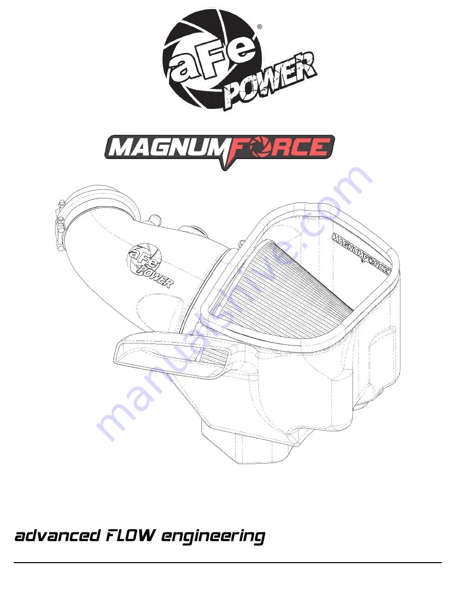
Magnum FORCE Stage-2 Cold Air Intake System


Instruction Manual


P/N: 54-13063D / 54-13063R

_____________________________


Make: 

Jeep     

Model: 

Grand Cherokee (WK2) SRT

   Year: 

2012-2021

   Engine: 

V8-6.4L 

Make: 

Dodge  

Model: 

Durango SRT                            

Year: 

2018-2021

   Engine: 

V8-6.4L


Summary of Contents for MAGNUM FORCE 54-13063D

Page 1: ...Cold Air Intake System Instruction Manual P N 54 13063D 54 13063R_____________________________ Make Jeep Model Grand Cherokee WK2 SRT Year 2012 2021 Engine V8 6 4L Make Dodge Model Durango SRT Year 2018 2021 Engine V8 6 4L ...

Page 2: ... Coupling Silicone Bellow 05 01555 E 1 Clamp T bolt 4 1 16 4 3 8 SS 03 50262 F 1 Clamp T bolt 3 9 16 3 7 8 SS 03 50498 G 1 Seal Trim 3 4 Bulb 32 Length 05 01507 H 1 Hose 5 8 ID 7 Length 05 01502 I 2 Spring Clamp 03 50646 J 1 Fitting Air Temp Sensor 05 01454 K 1 Grommet Rubber 03 50167 Installation will require the following tools 8mm and 11mm nut driver or socket socket wrench flat head screwdrive...

Page 3: ...Page 3 A1 A2 B E C D G F J K I H I ...

Page 4: ...r to Figure A for Steps 1 3 Step 1 Disconnect the temperature sensor Step 2 Using an 8mm nut driver loosen the hose clamps at the throttle body Step 3 Remove the driver s side valve cover REMOVAL Figure A REMOVAL ...

Page 5: ...he crankcase vent CCV line from the engine and pull the hose away from the engine This hose will be replaced Step 5 Remove the factory intake Carefully pull the factory intake tube away from the throttle body and pull up on the factory airbox Figure B REMOVAL ...

Page 6: ...Page 6 Refer to Figure C for Step 6 Step 6 Remove the factory block off plate Use a panel popper to remove the two 2 pins and three 3 clips from the factory trim seal REMOVAL Figure C ...

Page 7: ...Page 7 Refer to Figure D for Step 7 Step 7 Install the supplied coupling and clamps onto the throttle body Do not tighten the clamps INSTALL Figure D ...

Page 8: ...Page 8 Refer to Figure E for Step 8 Step 8 Transfer the three 3 factory grommets from the factory airbox to the aFe POWER housing INSTALL Figure E ...

Page 9: ...op then slip the air filter mouth into the oval opening on the aFe POWER housing making sure the air filter s lip locks into place Step 10 Place the clamp over the flange of the air filter and position it as shown in Figure F Do not tighten at this time Step 11 Install the supplied trim seal on the top edge of the aFe POWER housing INSTALL Figure H Figure F ...

Page 10: ...rature sensor from the factory intake tube to the aFe POWER intake tube Carefully pull up on the sensor to remove from the factory intake Then install the sensor into the aFe POWER intake tube by pushing it into the fitting and rotating clockwise quarter turn keeping it from sliding out Step 14 Insert the aFe POWER intake tube into the pre assembled aFe POWER housing and air filter Do not tighten ...

Page 11: ...Page 11 Refer to Figure H for Step 15 Step 15 Install the supplied hose and one 1 supplied clamp onto the engine s CCV opening Figure H INSTALL ...

Page 12: ...ousing in to the three 3 mounting pins Slide the aFe POWER intake tube into the coupling at the throttle body Step 17 Align the aFe POWER housing to the opening from Step 6 Step 18 Connect the open end of the supplied hose from Step 15 Use the remaining supplied clamp Label I to tighten to the aFe POWER intake tube INSTALL Figure I ...

Page 13: ... then tighten all three 3 clamps Step 21 Re install the factory valve cover Step 22 Re attach the factory trim seal from Step 6 and attach to the aFe POWER housing Step 23 Make sure all components and connections are secure Your installation is now complete Thank you for choosing aFe POWER NOTE Check all bolts clamps and connectors after 100 200 miles INSTALL Figure J ...

Page 14: ...Page 14 Page left blank intentionally ...

Page 15: ...Page 15 Page left blank intentionally ...

Page 16: ...252 Granite Street Corona CA 92879 https afepower com contact 8 9 2021 JTP ...

Reviews: