R01.43
22.10.2018
Page 19
Assembly of the device
To enable the aflex to work with reliable functionality, follow the steps below. In case
of non-observance a fault-free operation can not be guaranteed.
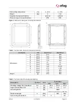
3.2.1 Drilling picture for assembly
Figure 4: Drilling picture in assembly level
Table 8: Size for drilling picture
3.2.2 Dimensions of the base plate
The aflex must be mounted on a plate with a minimum weight of 30kg. Otherwise the
performance of the aflex is restricted.
If two aflexs are installed in immediate proximity to one another, care must be taken
that the mounting plates have the stated minimum mass as well as a vibration
decoupling from each other. This decoupling is also applicable if vibrations or shocks
are to be expected by other components of the application.
For vibration decoupling, we recommend detachable damping elements which can
compensate for movements in X-Y-Z directions and are released in total for a mass
of at least 40 kg.
Figure 5: Assembly example in series
Description
aflex150 qc
aflex200qc
Drilling distance X in [mm]
176
261
Drilling distance Y in [mm]
70
110
Diameter of the central bore in [mm]
100
Diameter of the 4 fixing bores in [mm]
12.7
-0,3


