14
Note:
Once the tubing has been pushed into the nut it cannot
be pulled out. The nut will need to be removed. See Figure 14
for correct assembly.
1. Hand tighten the nut until the connection is tight.
Figure 14
Overflow Line Connection
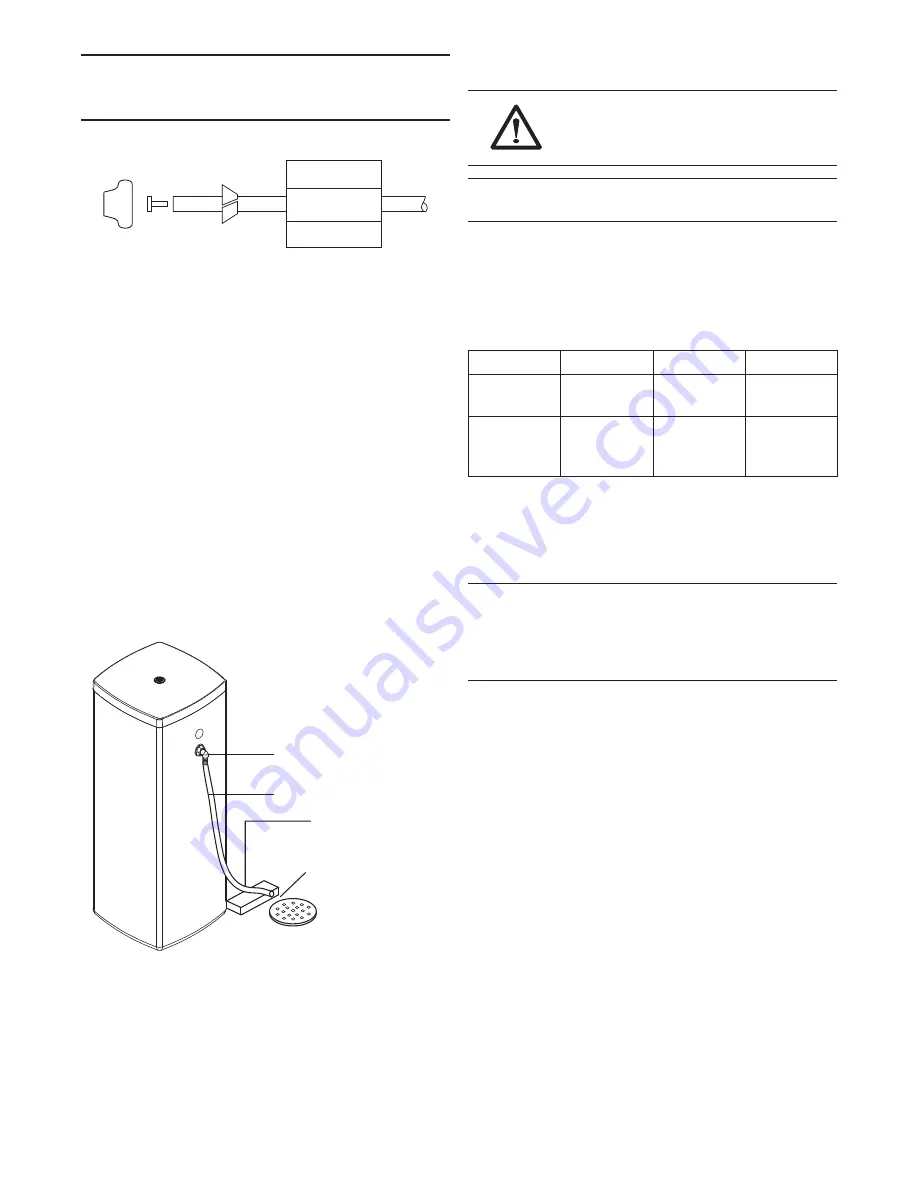
In the event of a malfunction, the brine TANK OVERFLOW will
direct “overflow” to the drain instead of spilling on the floor.
This fitting should be on the side of the cabinet. Most tank
manufacturers include a post for the tank overflow connector.
To connect the overflow line, locate the tubing connector on side
of tank, Figure 15. Attach length of 1/2-inch (1.3-cm) I.D. tubing
to fitting and run to drain. Do not elevate overflow line higher than
overflow fitting.
Do not tie into drain line of control unit. Overflow line must be a
direct, separate line from overflow fitting to drain, sewer or tub.
Allow an air gap as per drain line instructions.
Figure 15
Electrical Connection
WARNING:
This valve and control are for
dry location use only, unless used with a Listed
Class 2 Power Supply suitable for outdoor use.
Note:
There are no user serviceable parts in the AC adapter,
motor or the control board.
All controllers operate on a 12-volt alternating current power
supply. This requires use of the Pentair Water supplied AC adapter.
A variety of AC adapters are available for different applications.
These AC adapters are available from your supplier. They include:
AC Adapter
Input Voltage Application
Part Number
Standard
wall-mount
120V 60 Hz
UL listed for
dry locations
1000811
Outdoor rated
120V 60 Hz
UL listed
for outdoor
installations
1235448
120V AC Adapters:
Make sure power source matches the rating printed on the AC
adapter.
Note:
The power source should be constant. Be certain the AC
adapter is not on a switched outlet. Power interruptions longer
than eight hours may cause the control to lose the day and time
settings. When power is restored, the day and time settings
must be re-entered.
Controller Location
The controllers are designed to be mounted on the valve or
attached to a flat surface. Installations that do not provide easy
access to the valve can have the controller mounted for remote
operation.
A remote mount connection, PN 1256257, is available for the
WC300 Series controller.
Drain Tubing
Drain
Overflow Fitting
Secure hose in place
Air Gap
Summary of Contents for Origins WC300
Page 1: ...Operation Manual 00947 1821 EA 03671...
Page 33: ...Manuel d utilisation 00947 1821 EA 03671 A D O U C I S S E U R D E AU WC300...
Page 66: ...66...
Page 67: ...67...


