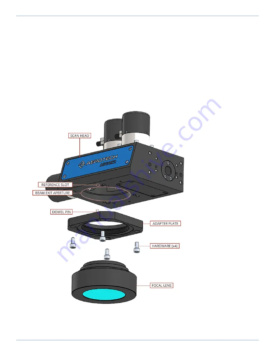
1. Before you assemble the focal lens into the scan head, remove the dust cover(s) and inspect the
lens elements and protective glass for dirt, scratches or cracks. Any lens component with a
scratch or a crack must be replaced.
2. If the optics are dirty, use the procedure outlined in
to clean them.
3. If necessary, use the clamp ring to install the protective glass over the front of the lens. Place the
dust cover over the front of the lens.
4. Remove the plug from the beam exit aperture on the bottom of the scan head.
5. Make sure that the dowel pin in the lens adapter is aligned with the reference slot in the scan
head and attach the lens adapter to the scan head using the appropriate hardware. The screw
length must be long enough to provide at least 1.0x diameter thread engagement.
6. Screw the focal lens into the lens adapter until it seats and is positioned securely. Be careful not
to cross-thread the housing of the lens assembly.
7. Remove the dust cover from the front of the focal lens.
To remove the focal lens, reverse the procedure outlined above.
Figure 2-3:
Assembly of Focal Lens to Scan Head (AGV-SPO)
AGV-SPO Hardware Manual
2.4. Attaching the Focal Lens to the Scan Head
www.aerotech.com
27
Summary of Contents for AGV-SPO Series
Page 1: ...Revision 2 00 AGV SPO Single Pivot Point Galvo Scanner HARDWARE MANUAL...
Page 6: ...This page intentionally left blank List of Tables AGV SPO Hardware Manual 6 www aerotech com...
Page 12: ...This page intentionally left blank Laser Shutter AGV SPO Hardware Manual 12 www aerotech com...
Page 16: ...Figure 1 2 Standard AGV SPO Chapter 1 Overview AGV SPO Hardware Manual 16 www aerotech com...


