


Chapter 2 Installation
Setting up the hardware
12
2201 ProLock
Setting up the hardware
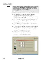
In order to set up the test system, proceed as follows:
1
Connect the cable of the power supply to the
DC In
plug that
is located on the rear panel of the 2201 ProLock.
2
Connect one end of the AC power cord to the power supply,
and the other to an AC power outlet.
3
Connect the
RF I
N
/O
UT
plug on ProLock’s rear panel with the
RF shield using a double-shielded RF cable. If you do not
intend to use the an Aeroflex RF shield, connect the 2201
ProLock to the coupling device of your choice.
Summary of Contents for ProLock 2201
Page 1: ...2201 ProLock 3G Test Set for Service Getting Started Manual AG295003 Issue 1 ...
Page 2: ......
Page 8: ...Table of contents vi 2201 ProLock ...
Page 20: ...Safety notes Declaration of EU Conformity xviii 2201 ProLock ...
Page 28: ...Chapter 1 Overview System architecture 8 2201 ProLock ...
Page 36: ...Chapter 2 Installation Configuring the software 16 2201 ProLock ...
Page 48: ...Chapter 3 Operation Cleaning 28 2201 ProLock ...
Page 58: ...Appendix B Software licence and warranty 38 2201 ProLock ...