background image

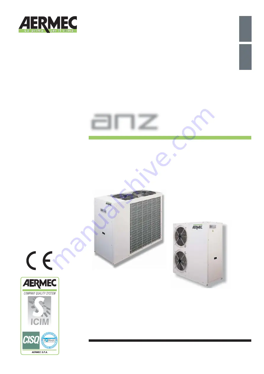
TECHNICAL MANUAL

Air-cooled heat pumps with high-efficiency scroll 
compressor

ISO 9001 - Cert. n° 0128/4

IANZTV. 0709 - 6755120_03

R

R407C

407C

anz


ENGLISH

MANUAL TÉCNICO

Bombas de calor condensadas por aire con compresor 
scroll de alta eficacia 

Español

Summary of Contents for ANZ 020

Page 1: ...ooled heat pumps with high efficiency scroll compressor ISO 9001 Cert n 0128 4 IANZTV 0709 6755120_03 R R407C 407C anz ENGLISH MANUAL TÉCNICO Bombas de calor condensadas por aire con compresor scroll de alta eficacia Español ...

Page 2: ...machine Versions available Description of components Accessories Technical data Operating limits Selection criteria Correction factors Cooling capacity and intake power versions H Ethylene glycol solution Sound data 1 2 3 This manual contains ...

Page 3: ...ity and Reliability If you do not know where our nearest After Sales Service Centre is you can get this from the dealership where the device was purchased The data might undergo modifications considered necessary for the improvement of the product Thank you again AERMEC S p A ENGLISH General standards 5 Description and choice of unit 6 Configurator 7 Component description 8 ELECTRONIC REGULATION 9...

Page 4: ...re II it has undergone the conformity testing procedure sizes ANZ from 0907 to 2007 A1 module with checks carried out by the appointed body RW TUV Kurfurstenstrasse 58 D 45138 ESSEN identity code 0044 2 designed manufactured and commercialized in compliance with the following technical specifications all models Harmonized standards EN 378 Refrigerating system and heat pumps Safety and environmen t...

Page 5: ...illers is suitable for producing warm cold water to use in hydronic systems the purpose of which is heating air conditioning Any use other than that permitted or outside the operating limits mentioned in this manual is forbidden if not previously agreed with the company The warranty does not include payment for damage due to wrong installation of the unit by the installer The warranty does not inc...

Page 6: ...able so that a great many different systems solutions can be catered for The electrical heating elements in the compressor are standard for the models The ANZ heat pumps can also be used in mixed fan coil radiator panel systems because of their special regulation control unit for the control of the radiator panels An incorporated heating element is also available that makes it possible to compensa...

Page 7: ...020 to 041 and basic control J With accumulation pump electric heater element incorporated for sizes from the 050 to the 200 and available as an accessory to be fitted externally for the 020 to the 041 and advanced control by which a three way valve not supplied can be managed Coil aluminium R copper S tinned copper V Made of aluminium with epoxy paint Evaporator According to PED standards Power s...

Page 8: ... resist atmospheric agents over time Fan unit Screw type statically and dynamically balanced The electric fans are protected electrically with magnetothermal switches and mechanically with anti intrusion metal grilles in accordance with the CEI EN 60335 2 40 standard Electrical components Electrical panel Contains the power section and the management of the controls and safety devices This conform...

Page 9: ... mode Models 020 025 030 041 are fitted with a flow switch positioned up line from the evaporator thermomagnetic compressor protection thermomagnetic fan protection thermomagnetic auxiliary protection fan power remote switch Microprocessor Evaporator inlet water temperature adjustment G Compressor start delay G Summer or winter functioning in the heat pump G with defrosting control Low temperature...

Page 10: ...exchangers It prevents the freezing of the water contained in the evaporator during winter pauses to be installed in the factory RA Electrical accumulation heating element Electrical accumulation heating element in the A versions It prevents the freezing of the water contained in the accumulation during winter pauses VT shock absorbers Set of four shock absorbers to fit under the steel base in the...

Page 11: ... 12 4 17 5 17 2 n a n a n a n a n a n a 400 V A 4 3 4 8 5 9 5 9 9 1 10 2 13 6 19 4 21 3 27 4 LRA 2 230 V A 75 0 78 0 99 0 113 0 n a n a n a n a n a n a 400 V A 32 0 40 0 46 0 52 0 65 0 77 0 100 0 130 0 170 0 202 0 Compressors type scroll Quantity n 1 1 1 1 1 1 1 1 1 1 Fans type Axial Quantity n 1 1 1 2 2 2 2 2 2 2 Air flow rate m3 h 2500 3300 3450 5300 7000 6700 6450 13450 12400 12000 Sound data S...

Page 12: ... 32 0 40 0 46 0 52 0 65 0 77 0 100 0 130 0 170 0 202 0 Compressors type H scroll Quantity H n 1 1 1 1 1 1 1 1 1 1 Fans type H Axial Quantity H n 1 1 1 2 2 2 2 2 2 2 Air flow rate H m3 h 2500 3300 3450 5300 7000 6700 6450 13450 12400 12000 Sound data Sound pressure 3 dB A 33 40 40 37 41 41 40 48 49 50 Evaporator type H Plates Quantity H n 1 1 1 1 1 1 1 1 1 1 Attachments IN ø 1 1 1 1 1 1 1 1 1 1 OUT...

Page 13: ... 8 LRA 2 230 V A 76 0 78 0 100 0 115 0 n a n a n a n a n a n a 400 V A 33 0 41 0 48 0 54 0 66 0 78 0 101 0 132 0 172 0 203 0 Compressors type scroll Quantity n 1 1 1 1 1 1 1 1 1 1 Fans type Axial Quantity n 1 1 1 2 2 2 2 2 2 2 Air flow rate m3 h 2500 3300 3450 5300 7000 6700 6450 13450 12400 12000 Sound data Sound pressure 3 dB A 33 40 40 37 41 41 40 48 49 50 Evaporator type Plates Quantity n 1 1 ...

Page 14: ...a n a n a n a 400 V A 33 0 41 0 48 0 54 0 66 0 78 0 101 0 132 0 172 0 203 0 Compressors type H scroll Quantity H n 1 1 1 1 1 1 1 1 1 1 Fans type HA Axial Quantity HA n 1 1 1 2 2 2 2 2 2 2 Air flow rate HA m3 h 2500 3300 3450 5300 7000 6700 6450 13450 12400 12000 Sound data Sound pressure 4 HA dB A 33 40 40 37 41 41 40 48 49 50 Evaporator type HA Plates Quantity HA n 1 1 1 1 1 1 1 1 1 1 Attachments...

Page 15: ...ed by the equipment N B The devices in their standard configurations are not suitable for installation in salty environments The maximum and minimum water flow rate limits are shown on the curves of the pressure drop diagrams Reference should be made to the diagram opposite for the operation limits Please contact the AERMEC technical sales office in the event it is necessary to operate the machine...

Page 16: ...trical capacity in conditions other than rated conditions are obtained by multiplying the Cf Processed water temperature t 5 C fig 02 Cooling capacity and input power rated values Pf Pa by the respective corrective coefficients Cft Cpa The diagram makes it possible to obtain the correction coefficients to be used for the chillers in cooling operation mode next each curve the external air temperatu...

Page 17: ...ielded and the input electrical capacity in conditions other than rated conditions are obtained by multiplying the rated values Pf Pa Ct Outside air temperature C B U fig 03 by the respective corrective coefficients Cft Cpa The diagram makes it possible to obtain the correction coefficients corresponding to each curve the temperature of the hot processed water referred to assuming a difference in ...

Page 18: ... D E F G H I L Water flow m3 h Pressure drop kPa Evaporator pressure drops 0 20 40 0 2 4 6 8 10 12 A B C Water flow m3 h Pressure drop kPa Water filter pressure drops A ANZ 0207 B ANZ 0257 C ANZ 0307 D ANZ 0417 E ANZ 0507 F ANZ 0807 G ANZ 0907 H ANZ 1007 I ANZ 1507 L ANZ 2007 Model 0207 0257 0307 0417 0507 0807 0907 1007 1507 2007 Water filter 1 Water filter 1 1 4 Water filter 1 1 2 Average water ...

Page 19: ...lume of water The table at the bottom of the page offers the maximum plant con tents for other operating conditions with glycol solutions The values are obtained by multiplying the reference value by the correction factor in the table below U M ANZ 0207 0257 0307 Hydraulic height m 30 25 20 15 10 Expansion tank calibration bar 3 2 2 7 2 2 1 7 standard Reference value water content 1 l 103 121 139 ...

Page 20: ...ht diffe rence is 15 metres the expansion tank calibration will be 1 8 bar If the calculation results below the stan dard calibration 1 5 bar no adjustment is required Hmax 55m H 12 25m Hmin H AN Fig 1 ANZ 0 20 40 60 80 100 120 140 160 0 1 2 3 4 5 6 7 8 9 10 11 m A B C D E F G H I Water flow m3 h Available static pressure kPa Available static pressure for plant A ANZ 0207 B ANZ 0257 C ANZ 0307 ANZ...

Page 21: ...vaporator pressure drop correction factor evaluated with an average temperature of 3 5 C FcGDpF b Correction factor of the pressure drops average temperature 0 5 C FcGDpF c Correction factor of the pressure drops average temperature 5 5 C FcGDpF d Correction factor of the pressure drops average temperature 9 5 C FcGDpF e Correction factor of the pressure drops average temperature 47 5 C FcGQF Flow...

Page 22: ... the percentage of glycol on the basis of the outside air temperature figure 03A you have to enter from the left hand axis and once you have intersected the curve you draw a vertical line which will intersect all the other curves in its turn The points obtained from the upper curves will represent the coefficients for the correction of the cooling capacity and input power for the flow rates and pr...

Page 23: ...fferent in heating mode C 0 3 2 19 9 Water temperature set in cooling mode C 7 11 25 Operating thermostat different in cooling mode C 0 3 2 19 9 Check parameters Protection device calibration 020 025 030 041 050 080 090 100 150 200 Auxiliary fan magneto thermal switch A 2 2 2 4 4 4 4 6 8 8 Compressor thermomagnetic switch A 230 V 16 20 20 20 n a n a n a n a n a n a 400 V 8 10 10 13 13 16 25 32 40 ...

Page 24: ...o be installed externally at the expense of the user The running of the heater is given over to an integrated control on the basis of the temperature of the water and the outside temperature In the AK versions a basic control is used and this switches on the heater when requested by the control logic The AJ versions are supplied with an advanced control which apart from enabling the supplementary ...

Page 25: ...ed valve Depending on the difference shown the control unit determines the activation of the opening and closing relays of the actuator The independence of the calculated temperature from the room temperature ensures stable working even in the event of sudden variations such as the opening of doors or windows To take into account the contribution of free heat for instance solar radiation when the ...

Page 26: ...mperature rL outside temperature at start of compensation r3 minimum temperature of the return water at rL rF maximum variation of the water temperature where r3 rF maximum temperature of return water rE incline of the water curve Refers to the example below heat set C C Outside air temperature Heat compensation logic for radiating panels C Outside air temperature heat set C Heat compensation logi...

Page 27: ...for electrical connections Female plumbing attachment diam 1 Microchiller ANZ 0207H 0257 H ANZ 0207HA 0257 HA 0207HK 0257HK 0207HJ 0257HJ Out In 352 900 850 140 250 515 5 50 155 200 Male plumbing attachment diam 1 Microchiller Out In 352 900 1 000 140 477 466 200 155 50 Att idraulici maschio Ø 1 Microchiller Holes for electrical connections ANZ 0307 H ANZ 0307 HA 0307HK 0307HJ Holes for electrical...

Page 28: ... 435 1 120 1 250 105 230 280 70 715 466 Out In Male plumbing attachment diam 1 Microchiller ANZ 050HA 080HA ANZ 0417HA 0417HK 0417HJ 435 1 120 1 250 431 5 108 80 400 450 45 Out In Female plumbing attachment diam 1 Microchiller 555 1 167 1 280 In Out 450 400 46 210 130 Female plumbing attachment diam 1 1 4 Microchiller Holes for electrical connections ANZ 0507H 080H ...

Page 29: ...0 466 400 420 360 Out In Male plumbing attachment diam 1 Microchiller ANZ 1007HA 1507HA 2007HA ANZ 0907HA 555 1 167 1 280 In Out 450 400 46 210 130 Female plumbing attachment diam 1 1 4 Microchiller 750 1 750 1 345 57 360 420 170 130 60 Out In Female plumbing attachment diam 1 1 2 Microchiller ANZ 1007H 1507H 2007H Holes for electrical connections Female plumbing attachment diam 1 1 4 1 580 ...

Page 30: ...30 Size data ANZ 0507 0807 With accumulation and electric heater ANZ 050HAK 050HAJ ANZ 080HAK 080HAJ ...

Page 31: ...31 Size data ANZ 0907 1007 With accumulation and electric heater ANZ 0907HAK 0907HAJ ANZ 1007HAK 1007HAJ ...

Page 32: ...32 Size data ANZ 1507 2007 With accumulation and electric heater ANZ 150HAK 150HAJ ANZ 200HAK 200HAJ ...

Page 33: ...onstante por lo que los productos AERMEC son sinónimo de Seguridad Calidad y Fiabilidad Sobre nuestro servicio de asistencia más cercano si se desconoce se puede obtener información en el concesionario donde ha adquirido al aparato Los datos pueden sufrir modificaciones consideradas necesarias para una mejora del producto Gracias de nuevo AERMEC S p A Información general Descripción de la máquina ...

Page 34: ...ica 35 Accesorios 36 Datos técnicos 37 Criterios de elección 41 Potencia de refrigeración y Potencia absorbida 42 Potencia térmica y Potencia absorbida 43 Solución de glicol etilénico 44 Factores correctivos para t distintos del nominal 46 Datos sonoros 46 Calibrado de los parámetros de control 46 Datos sobre las dimensiones 47 ...

Page 35: ...2007 con referencia al anexo II de dicha norma al siguiente procedimiento de comprobación de conformidad módulo A1 con controles efectuados mediante inspecciones por el organismo notifi cado RW TUV Kurfurstenstrasse 58 D 45138 ESSEN número de distinti vo 0044 2 diseñado producido y comercializado en el cumplimiento de las siguientes características técnicas todos los modelos Normas armonizadas EN ...

Page 36: ...ara producir agua caliente fría que se deba utilizar en instalaciones hídricas con el objetivo de calentamiento acondicionado Queda prohibido cualquier uso distinto del permitido o fuera de los límites de funcionamiento citados en el manual si antes no ha sido acordado con la empresa La garantía no cubre el pago de los daños causados por una instalación defectuosa por parte del instalador La garan...

Page 37: ...bajo de ruido Se encuentran disponibles en montajes distintos para poder satisfacer una gran variedad de soluciones de instalación Las resistencias eléctricas de los compresores son de serie para los modelos Las bombas de calor ANZ pueden utilizarse también en sistemas mixtos fan coil losas radiantes gracias a una centralita de ajuste específica para el control de las losas radiantes además tambié...

Page 38: ...encia eléctrica integrada para los tamaños del 050 al 200 y disponible como accesorio para un montaje externo para las medidas de 020 a 041 y control evolucionado con el que es posible manejar una válvula de tres vías no suministrada Baterías En aluminio R en cobre S Cobre restañado V En aluminio con barniz epóxico Evaporador Conforme PED Alimentación 3 400V 50Hz M 1 230V 50Hz sólo para tamaños de...

Page 39: ...entes atmosféricos GRUPO DE VENTILACIÓN De tipo helicoidal y equilibrado estática y dinámicamente Los electroventiladores están protegidos eléctricamente con interruptores magnetotérmicos y mecánicamente con rejillas metálicas anti intrusión según las normativas CEI EN 60335 2 40 Componentes eléctricos cuadro eléctrico Contiene la sección de potencia y la gestión de los controles y seguridades Est...

Page 40: ...ujostato situado encima del evaporador magnetotérmico protección compresores m a g n e t o t é r m i c o p r o t e c c i ó n ventiladores magnetotérmico protección auxiliar telerruptor alimentación ventiladores Microprocesador Regulación temperatura entrada agua evaporador G Retraso puesta en marcha compresor G Funcionamiento estivo o invernal en bomba de calor G con función desescarche Función di...

Page 41: ...a eléctrica intercambiadores Resistencia eléctrica para el intercambiador helicoidal Evita el congelamiento del agua contenida en el evaporador durante las pausas invernales a instalar en sede RA Resistencia eléctrica acumulación Resistenciaeléctricaparaacumulador en las modelos A Evita el congelamiento del agua contenida en el acumulador durante las pausas invernales VT soportes antivibración Gru...

Page 42: ...1 12 4 17 5 17 2 n d n d n d n d n d n d 400V A 4 3 4 8 5 9 5 9 9 1 10 2 13 6 19 4 21 3 27 4 LRA 2 230V A 75 0 78 0 99 0 113 0 n d n d n d n d n d n d 400V A 32 0 40 0 46 0 52 0 65 0 77 0 100 0 130 0 170 0 202 0 Compresores Tipo scroll Cantidad n 1 1 1 1 1 1 1 1 1 1 Ventiladores Tipo Axial Cantidad n 1 1 1 2 2 2 2 2 2 2 Caudal aire m3 h 2500 3300 3450 5300 7000 6700 6450 13450 12400 12000 datos so...

Page 43: ...6 0 52 0 65 0 77 0 100 0 130 0 170 0 202 0 Compresores Tipo h scroll Cantidad h n 1 1 1 1 1 1 1 1 1 1 Ventiladores Tipo h Axial Cantidad h n 1 1 1 2 2 2 2 2 2 2 Caudal aire h m3 h 2500 3300 3450 5300 7000 6700 6450 13450 12400 12000 datos sonoros Presión sonora 3 dB A 33 40 40 37 41 41 40 48 49 50 Evaporador Tipo h Placas Cantidad h n 1 1 1 1 1 1 1 1 1 1 Conexiones IN ø 1 1 1 1 1 1 1 1 1 1 OUT ø 1...

Page 44: ...3 3 28 8 LRA 2 230V A 76 0 78 0 100 0 115 0 n d n d n d n d n d n d 400V A 33 0 41 0 48 0 54 0 66 0 78 0 101 0 132 0 172 0 203 0 Compresores Tipo scroll Cantidad n 1 1 1 1 1 1 1 1 1 1 Ventiladores Tipo Axial Cantidad n 1 1 1 2 2 2 2 2 2 2 Caudal aire m3 h 2500 3300 3450 5300 7000 6700 6450 13450 12400 12000 datos sonoros Presión sonora 3 dB A 33 40 40 37 41 41 40 48 49 50 Evaporador Tipo Placas Ca...

Page 45: ...n d n d 400V A 33 0 41 0 48 0 54 0 66 0 78 0 101 0 132 0 172 0 203 0 Compresores Tipo h scroll Cantidad h n 1 1 1 1 1 1 1 1 1 1 Ventiladores Tipo HA Axial Cantidad HA n 1 1 1 2 2 2 2 2 2 2 Caudal aire HA m3 h 2500 3300 3450 5300 7000 6700 6450 13450 12400 12000 datos sonoros Presión sonora 4 HA dB A 33 40 40 37 41 41 40 48 49 50 Evaporador Tipo HA Placas Cantidad HA n 1 1 1 1 1 1 1 1 1 1 Conexione...

Page 46: ...os datos concernientes a la presión y a la potencia sonora emitidas por los aparatos NOTA En su configuración estándar los aparatos no son adecuados para una instalación en ambiente salino Los límites máximos y mínimos de caudal de agua están indicados por las curvas de los diagramas de las pérdidas de carga Para obtener los límites de funcionamiento consulte el diagrama siguiente En el caso de qu...

Page 47: ...intas de las nominales se obtienen multiplicando los valores nominales Cf Temperatura del agua producida t 5 C fig 02 potencia de refrigeración y POTENCIA ABSORBIDA Pf Pa por los respectivos coeficientes correctivos Cf Ca El diagrama siguiente permite obtener los coeficientes correctivos que se deben utilizar para los enfriadores con el funcionamiento en frío con cada curva se encuentra correspond...

Page 48: ...a eléctrica absorbida en condiciones diversas de las nominales se obtienen multiplicando los valores nominales Pf Pa que aparecen al Ct Temperatura externa C B U fig 03 pie de la página para los respectivos coeficientes correctivos Cf Ca El siguiente diagrama permite obtener los coeficientes correctivos en coincidencia con cada curva se encuentra indicada la temperatura del agua caliente producida...

Page 49: ...80 100 120 0 2 4 6 8 10 12 A B C D E F G H I L Caudal de agua m3 h Pérdida de carga kPa Pérdida de carga evaporador 0 20 40 0 2 4 6 8 10 12 A B C Caudal de agua m3 h Pérdida de carga kPa Pérdidas de carga filtro agua A ANZ 0207 B ANZ 0257 C ANZ 0307 D ANZ 0417 E ANZ 0507 F ANZ 0807 G ANZ 0907 H ANZ 1007 I ANZ 1507 L ANZ 2007 Mod 0207 0257 0307 0417 0507 0807 0907 1007 1507 2007 Filtro 1 Filtro 1 1...

Page 50: ... necesario instalar un ulterior depósito de expansión adicional cuyo tamaño se debe deter minar utilizando los criterios habitua les con referencia al volumen de agua adicional En el cuadro presente en el fondo de la página se pueden obtener los valores de máximo contenido de la insta lación también para otras condiciones de funcionamiento con agua glicolada Los valores se obtienen multiplicando e...

Page 51: ...se inferior al valor de la regulación estándar 1 5 bar no efectuar ninguna regulación Verificar que el utilizador más bajo pueda soportar la presión global que actúa en ese punto Hmax 55m H 12 25m Hmin H AN Fig 1 ANZ 0 20 40 60 80 100 120 140 160 0 1 2 3 4 5 6 7 8 9 10 11 m A B C D E F G H I Caudal de agua m3 h Prevalencia útil kPa Prevalencia útil a la instalación A ANZ 0207 B ANZ 0257 C ANZ 0307...

Page 52: ...tor de corrección de las pérdidas de carga evaporador temp media 3 5 C FcGDpF b factor de corrección de las pérdidas de carga temperatura media 0 5 C FcGDpF c factor de corrección de las pérdidas de carga temperatura media 5 5 C FcGDpF d factor de corrección de las pérdidas de carga temperatura media 9 5 C FcGDpF e factor de corrección de las pérdidas de carga temperatura media 47 5 C FcGQF factor...

Page 53: ...iones iniciales En el caso de que se desee calcular el porcentaje de glicol en función a la temperatura del aire externo figura 03A se tendrá que acceder por el eje izquierdo y una vez intersecada la curva se procederá a trazar una línea vertical la cual a su vez interceptará las demás curvas Los puntos obtenidos de las curvas superiores representan los coeficientes para la corrección de la potenc...

Page 54: ...ío C 0 3 2 19 9 Parámetros de control Ajuste de los dispositivos de protección 020 025 030 041 050 080 090 100 150 200 Magnetotérmico auxiliar ventiladores A 2 2 2 4 4 4 4 6 8 8 Magnetotérmico compresor A 230V 16 20 20 20 n d n d n d n d n d n d 400V 8 10 10 13 13 16 25 32 40 50 Presostato alta presión bar 28 28 28 28 28 28 28 28 28 28 Presostato baja presión bar 1 1 1 1 1 1 1 1 1 1 3 5 8 10 Facto...

Page 55: ...ida para sistemas con losas radiantes IN OUT 1 2 3 IN OUT 1 2 3 5 ANZ AK 0507 0807 0907 1007 1507 2007 4 IN OUT 1 3 ANZ AK 0207 0257 0307 0417 OUT 5 4 IN 1 3 ANZ AJ 0507 0807 0907 1007 1507 2007 ANZ AJ 0207 0257 0307 0417 Resistencia eléctrica BKW Accessorios ANZ K J 0207 0257 0307 0417 BW4KW230 BW4KW400 BW5KW230 BW5KW400 Consumos eléctricos Versión U M 0207 0257 0307 0417 0507 0807 0907 1007 1507...

Page 56: ...ura de puertas o ventanas Para tener en cuenta los aportes de calor gratuitos por ejemplo la radiación solar cuando la sonda ambiente detecta una temperatura 2 grados superior al set point el relé de cierre de la válvula se activa para interrumpir la alimentación de agua caliente proveniente de la bomba de calor A Reducción set point en calentamiento B Pendiente C no utilizado D no utilizado E Set...

Page 57: ...el agua de regreso rE Inclinación de la gráfica del agua Hace referencia al ejemplo de abajo rF max r3 min T rL set en calor C C Temperatura externa Lógica de compensación en calor para losas radiantes 15 10 5 0 5 10 15 20 C 30 31 32 33 34 35 36 37 38 39 40 41 42 43 44 45 C rE 4 3 r E 1 6 3 r E 1 rE 0 72 rE 0 57 rE 0 46 rE 0 39 rE 0 25 26 27 28 29 C Temperatura externa set en calor C Lógica de com...

Page 58: ...207HA 0257 HA 0207HK 0257HK 0207HJ 0257HJ Out In 352 900 850 140 250 515 5 50 155 200 Microchiller Out In 352 900 1 000 140 477 466 200 155 50 Microchiller ANZ 0307 H ANZ 0307 HA 0307HK 0307HJ Orificios para conexiones eléctricas Orificios para conexiones eléctricas Orificios para conexiones eléctricas Conex hidráulicas macho Ø 1 Conex hidráulicas macho Ø 1 Conex hidráulicas macho Ø 1 Conex hidráu...

Page 59: ...ller ANZ 050HA 080HA ANZ 0417HA 0417HK 0417HJ 435 1 120 1 250 431 5 108 80 400 450 45 Out In Microchiller 555 1 167 1 280 In Out 450 400 46 210 130 Microchiller ANZ 0507H 080H Orificios para conexiones eléctricas Orificios para conexiones eléctricas Conex hidráulicas macho Ø 1 Conex hidráulicas macho Ø 1 Conex hidráulicas macho Ø 1 Conex hidráulicas hembra Ø 1 1 4 ...

Page 60: ...A 2007HA ANZ 0907HA 555 1 167 1 280 In Out 450 400 46 210 130 Microchiller 750 1 750 1 345 57 360 420 170 130 60 Out In Microchiller ANZ 1007H 1507H 2007H Orificios para conexiones eléctricas Orificios para conexiones eléctricas Conex hidráulicas macho Ø 1 Conex hidráulicas macho Ø 1 Conex hidráulicas hembra Ø 1 1 4 Conex hidráulicas hembra Ø 1 1 4 Conex hidráulicas hembra Ø 1 1 2 1 580 ...

Page 61: ...Z 0507 0807 Con acumulación y resistencia eléctrica ANZ 050HAK 050HAJ ANZ 080HAK 080HAJ Orificios para conexiones eléctricas Orificios para conexiones eléctricas Conex hidráulicas hembra Ø 1 1 4 Conex hidráulicas hembra Ø 1 1 4 ...

Page 62: ...Z 0907 1007Con acumulación y resistencia eléctrica ANZ 0907HAK 0907HAJ ANZ 1007HAK 1007HAJ Orificios para conexiones eléctricas Conex hidráulicas hembra Ø 1 1 4 Conex hidráulicas hembra Ø 1 1 2 Conex hidráulicas hembra Ø 1 1 2 ...

Page 63: ...s ANZ 1507 2007 Con acumulación y resistencia eléctrica ANZ 150HAK 150HAJ ANZ 200HAK 200HAJ Conex hidráulicas hembra Ø 1 1 2 Conex hidráulicas hembra Ø 1 1 2 Conex hidráulicas hembra Ø 1 1 2 Conex hidráulicas hembra Ø 1 1 2 ...

Page 64: ...442 93566 www aermec com I dati tecnici riportati sulla seguente documentazione non sono impegnativi L Aermec si riserva la facoltà di apportare in qualsiasi momento tutte le modifiche ritenute necessarie per il miglioramento del prodotto carta riciclata recycled paper papier recyclé recycled Papier ...

Reviews: