background image

GF-135


 Esteem 399 Low NOx Boiler


Chapter 5


OMM-0089_0A


Installation, Operation & Maintenance Manual


Boiler Piping 


Page 

36

 of 

188


AERCO International, Inc. 

 100 Oritani Dr. 

  Blauvelt, NY 10913  

OMM-0089_0A


MC1 06/19/14


Ph.: 800-526-0288 


5.16  SYSTEM PIPING—SPECIAL APPLICATIONS 

If the boiler is used in conjunction with a chilled water/medium system, the boiler and chiller 
must be piped in parallel. Install flow/check valves to prevent the chilled medium from entering 
into the boiler. 

If the boiler is used to supply hot water to the heating coils of an air handler where they may 
be exposed to chilled air circulation, install flow/check valves or other automatic means to 
prevent gravity circulation of the boiler water during cooling cycles. 

5.17  SYSTEM PIPING—MULTIPLE UNITS INSTALLATION 

Use a balanced manifold system as the primary / secondary connection to the space heating 
piping as shown in Figure 5-9

.


Maintain a minimum of 6 inches [153 mm] of clearance between units to allow for servicing. 

Refer to Figure 5-3 and Figure 5-4


to install air separator and expansion tank. 

For the space heating piping refer to the applications mentioned in this manual or  use 
recognized design methods. 

NOTE 

The boiler system piping shown must be a “closed” system to 
avoid any contamination and potential failure of any components 
in the system. 


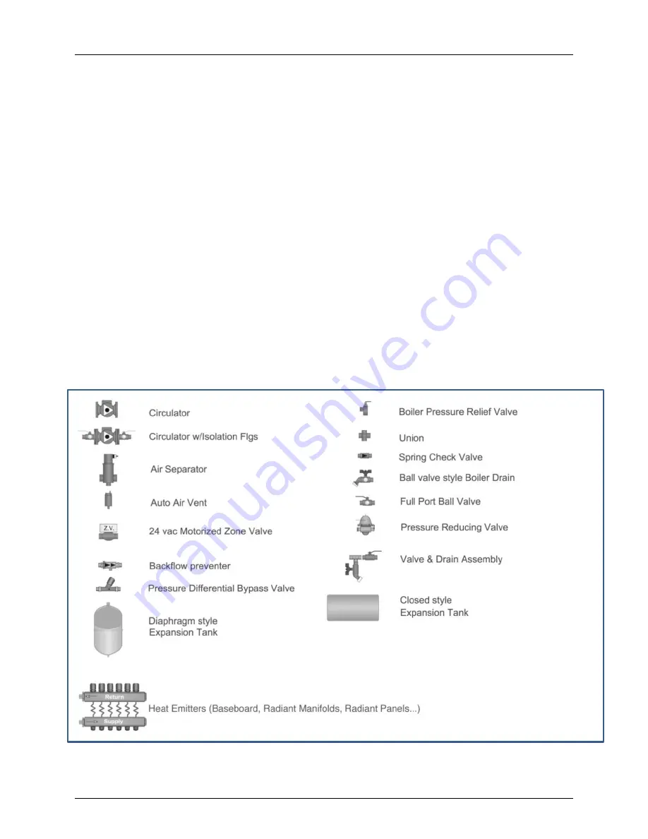
Figure 5-2: Piping Diagram Component Legend 

Summary of Contents for esteem

Page 1: ... AERCO International Inc 100 Oritani Dr Blauvelt NY 10913 OMM 0089_0A MC1 06 19 14 Ph 800 526 0288 GF 135 OMM 0089_0A USER MANUAL Installation Operation and Maintenance GAS FIRED BOILER Natural Gas or Propane Gas Modulating Condensing Hot Water Boiler 06 19 2014 ...

Page 2: ...ument some types of information are presented as shown in the following examples Message Type Example and Description NOTES NOTE NOTE messages indicate specific information related to the surrounding contextual information and highlighted for special attention CAUTIONS CAUTION CAUTION messages inform of potential problems relating to the functioning of equipment safety to persons harm to the envir...

Page 3: ...5 METHODS OF SUPPLYING COMBUSTION AIR TO A CONFINED SPACE CATEGORY IV 21 3 5 1 INDOOR COMBUSTION AIR 22 3 5 2 OUTDOOR COMBUSTION AIR 23 3 5 2 1 Option 1 One Permanent Opening to Outside 23 3 5 2 2 Option 2 Two Permanent Openings to Outside 24 3 6 COMBINATION OF INDOOR AND OUTDOOR COMBUSTION AIR 25 3 6 1 Outdoor Opening s Location 25 3 6 2 Outdoor Opening s Size 25 3 7 COMBUSTION AIR AND VENT PIPIN...

Page 4: ...E GAS 47 7 3 1 Pipe Sizing Propane Gas 47 7 3 2 Propane Gas Supply Pressure Requirements 48 CHAPTER 8 INTERNAL WIRING 51 8 1 GENERAL REQUIREMENTS 51 8 2 FUSE LOCATIONS 51 8 2 1 EZ SETUP Controller Module Fuses Location 51 8 2 2 Line Voltage Fuses Location 52 CHAPTER 9 EXTERNAL WIRING 55 9 1 INSTALLATION COMPLIANCE 55 9 2 LINE VOLTAGE CONNECTIONS 55 9 3 CIRCULATOR WIRING 56 9 4 ALARM WIRING 57 9 5 ...

Page 5: ...CKOUT HISTORY 80 10 13 1 Lockout Details 80 CHAPTER 11 START UP PREPARATION 85 11 1 CHECK BOILER SYSTEM WATER CHEMISTRY 85 11 1 1 Water pH Level 6 0 to 8 0 85 11 1 2 Water Hardness Less Than 7 Grains 85 11 1 3 Chlorinated Water 85 11 1 4 Flush Boiler to Remove Sediment 85 11 1 5 Check and Test Antifreeze 86 11 1 6 Use of Antifreeze in the Boiler System 86 11 2 BOILER CLEANING 86 11 2 1 Cleaning an...

Page 6: ...7 1 REPORTED PROBLEMS 109 17 2 SURROUNDING AREA INSPECTION 109 17 3 BURNER AREA INSPECTION 109 17 4 SYSTEM PIPING INSPECTION 110 17 5 CLEAN CONDENSATE DRAIN ASSEMBLY 110 17 6 VENTILATION AIR OPENINGS INSPECTION 110 17 7 VENT AND COMBUSTION AIR PIPING INSPECTION 110 17 8 BOILER SYSTEM INSPECTION 111 17 9 EXPANSION TANK INSPECTION 111 17 10 BOILER RELIEF VALVE INSPECTION 111 17 11 IGNITION ELECTRODE...

Page 7: ... Default CH1 CH2 130 18 4 DHW SETTINGS MENU 135 18 4 1 DHW Operation Default Enabled 136 18 4 2 Demand Type Default Switch 137 18 4 3 Boiler DHW Setpoint Default 186 F 86 C 137 18 4 4 DHW Storage Setpoint Default 140 F 60 C 137 18 4 5 DHW on Differential Default 6 F 3 C 138 18 4 6 DHW Storage Adder Default 46 F 25 C 139 18 4 7 DHW Post Pump Time Default 1 Minute 139 18 4 8 DHW Priority Timeout Def...

Page 8: ...Boiler Disabling Algorithm 161 18 9 7 Maximum Firing Rate Default 398 MBH 161 18 9 8 CH or DHW Boilers Default 0 162 18 9 9 Automatic Rotation Default Enabled 163 18 9 10 CH Proportional Gain Default 7 164 18 9 11 CH Integral Gain Default 245 165 18 9 12 DHW Proportional Gain Default 7 166 18 9 13 DHW Integral Gain Default 245 167 18 9 14 Modbus Address Default 0 BcST 168 18 9 15 Modbus Interface ...

Page 9: ...gral part of the product and must be maintained in legible condition It must be given to the user by the installer and kept in a safe place for future reference Installation and service must be performed by a qualified installer service agency or the gas supplier WARNING Do not use matches candles flames or other sources of ignition to check for gas leaks Prior to installing this product read all ...

Page 10: ...er water WARNING Should overheating occur or the gas supply fails to shut off turn OFF the manual gas control valve external to the appliance DO NOT add cold make up water when the boiler is hot Thermal shock can cause potential cracks in the heat exchanger WARNING IF YOU SMELL GAS Do Not try to light any appliance Do Not touch any electrical switch Do Not use any phone or cell phone in your build...

Page 11: ...f Valve 1 3 PROLONGED SHUTDOWN After prolonged shutdown it is recommended that the startup procedures and the safety device test procedures in Chapter 12 of this manual be performed to verify all system operating parameters If there is an emergency turn off the electrical power supply to the AERCO boiler and close the manual gas valve located upstream from the unit The installer must identify the ...

Page 12: ...erated or hard wired carbon monoxide detector with an alarm is installed on each additional level of the dwelling building or structure served by the side wall horizontal vented gas fueled equipment It shall be the responsibility of the property owner to secure the services of qualified licensed professionals for the installation of hard wired carbon monoxide detectors a In the event that the side...

Page 13: ...g system shall include 1 Detailed instructions for the installation of the venting system design or the venting system components and 2 A complete parts list for the venting system design or venting system d MANUFACTURER REQUIREMENTS GAS EQUIPMENT VENTING SYSTEM NOT PROVIDED When the manufacturer of a Product Approved side wall horizontally vented gas fueled equipment does not provide the parts fo...

Page 14: ...r Chapter 1 OMM 0089_0A Installation Operation Maintenance Manual Safety Precautions Page 14 of 188 AERCO International Inc 100 Oritani Dr Blauvelt NY 10913 OMM 0089_0A MC1 06 19 14 Ph 800 526 0288 This page left intentionally blank ...

Page 15: ...GA B149 1 or B149 2 Canadian Electrical Code Part 1 CSA C22 1 Standards for Controls and Safety Devices for Automatically Fired Boilers ANSI ASME CSD 1 when required NOTE The Esteem 399 Low NOx boiler gas manifold and gas controls meet the safe lighting and other performance requirements as specified in ANSI Z21 13 latest edition 2 2 DETERMINING PRODUCT LOCATION Before locating the Esteem 399 Low ...

Page 16: ...eeze protection within the boiler system See the warning in section 17 22 Handling Previously Fired Combustion Chamber Insulation 2 4 RECOMMENDED CLEARANCES The Esteem 399 Low NOx is approved for zero clearance to combustibles excluding vent and boiler piping Boiler Piping 1 4 inch from combustible materials See Vent System Installation Supplement GF 125V for vent clearance requirements To provide...

Page 17: ...s controls are no less than 18 inches 458 mm above the floor level Locate or protect the unit in a manner so it cannot be damaged by a moving vehicle 2 6 BOILER FREEZE PROTECTION FEATURE The boiler control has a freeze protection feature built in This feature monitors the boiler temperature and responds as follows when no call for heat is present 46ºF 8ºC CH 1 Auxiliary Boiler Pumps ON 42ºF 6ºC CH...

Page 18: ...iler Chapter 2 OMM 0089_0A Installation Operation Maintenance Manual Installation Page 18 of 188 AERCO International Inc 100 Oritani Dr Blauvelt NY 10913 OMM 0089_0A MC1 06 19 14 Ph 800 526 0288 This page left intentionally blank ...

Page 19: ...s often contain fluorine or chlorine compounds When these chemicals pass through the burner and vent system they can form strong acids These acids can create corrosion of the heat exchanger burner components and vent system causing serious damage and presenting a possible threat of flue gas spillage or water leakage into the surrounding area Please read the information listed below If contaminatin...

Page 20: ...or combustion For Direct Vent installations involving only the Esteem boiler in which the minimum service clearances are maintained see Recommended Clearances section 2 4 no ventilation openings are required For Direct Vent zero clearance installations involving only the Esteem boiler the space enclosure must have two openings for ventilation The openings must be sized to provide 1 square inch of ...

Page 21: ...iance for combustion Piping uncontaminated combustion air directly from the outdoors to the appliance is recommended This reduces the risks associated with indoor contaminates flammable vapors and tight housing construction This practice also promotes higher system efficiency In installations where the Esteem boiler shares the space with air movers exhaust fan clothes dryers fireplaces etc and oth...

Page 22: ...l have a minimum free area of 1 sq in 1000 Btu hr of the total input rating of all gas utilization equipment in the space but not less than 100 sq inches One opening shall commence within 12 inches of the top and one opening shall commence within 12 inches of the bottom of the enclosure The minimum dimension of air openings shall be not less than 3 inches Combining spaces in different stories The ...

Page 23: ... One Permanent Opening Method See Figure 3 2 One permanent opening commencing within 12 inches of the top of the enclosure shall be provided The equipment shall have clearances of at least 1 inch from the sides and 6 inches from the front of the appliance The opening shall directly communicate with the outdoors or shall communicate through a vertical or horizontal duct to the outdoors or spaces th...

Page 24: ... with the outdoors or spaces that freely communicate with the outdoors as follows Where directly communicating with the outdoors or where communication to the outdoors is through vertical ducts each opening shall have a minimum free area of 1 sq in 4000 Btu hr of total input rating for all equipment in the enclosure See Figure 3 3 Figure 3 3 All Combustion Air from Outdoors Through Ventilated Atti...

Page 25: ...ommon vent with other gas or oil appliances This may cause flue gas spillage or appliance malfunction resulting personal injury death and or property damage 3 7 COMBUSTION AIR AND VENT PIPING WARNING Combustion air and vent piping must be sealed gas tight and meet all provided instructions and applicable codes failure to comply will result in severe personal injury or death The Esteem boiler requi...

Page 26: ...ractical close all building doors and windows and all doors between the space in which the appliances remaining connected to the common venting system are located and other spaces of the building Turn on clothes dryers and any appliance not connected to the common venting system Turn on any exhaust fans such as range hoods and bathroom exhausts so they will operate at maximum speed Do not operate ...

Page 27: ...llation shall be in strict compliance with the manufacturer s instructions A copy of the installation instructions shall remain with the appliance or equipment at the completion of the installation 4 A metal or plastic identification plate shall be mounted at the exterior of the building four feet directly above the location of vent terminal The plate shall be of sufficient size to be easily read ...

Page 28: ...oiler Chapter 3 OMM 0089_0A Installation Operation Maintenance Manual Comb Air Venting Page 28 of 188 AERCO International Inc 100 Oritani Dr Blauvelt NY 10913 OMM 0089_0A MC1 06 19 14 Ph 800 526 0288 This page intentionally blank ...

Page 29: ...floor installation is required an optional floor stand is available through AERCO International WARNING The wall used for mounting the Esteem 399 unit must be vertically plumbed and capable of supporting a minimum 250 pounds 115 kg Failure to comply with these requirements could result in personal injury death or substantial property damage 4 3 WALL MOUNTING GUIDELINES The boiler is heavy and bulk...

Page 30: ...uestionable in supporting a minimum weight of 250 pounds 115 kg it is recommended to use the optional floor stand Wall Bracket Installation Solid Walls Locate the general area of the boiler placement Place the wall mounting bracket on the wall ensuring the upper edge of the bracket is away from the wall Level the bracket and use a pencil to mark the location of the mounting slots on the wall Remov...

Page 31: ...ge piping can result in personal injury death or substantial property damage The Esteem 399 Low NOx boiler is supplied with a 80 psi pressure relief valve and must be piped using the PRV connection as shown in Figure 5 1 To avoid potential water damage to the surrounding area or potential scalding hazard due to the operation of the relief valve the discharge piping o Must be connected to the disch...

Page 32: ...nt on initial installation Never loosen the hygroscopic cap to allow air to escape the air vent Air will exit with the cap fully tightened in place If the hygroscopic cap is not fully tightened water may leak from the cap Simply tighten the cap securely 5 4 LOW WATER CUTOFF DEVICE The Esteem boiler is equipped with a factory installed pressure switch type Low Water Cut Off device The minimum opera...

Page 33: ...erminal strip This will provide a hard lockout requiring a manual reset of the control 5 6 BACKFLOW PREVENTER Use a backflow preventer valve in the make up water supply to the unit as required by local codes 5 7 BOILER SYSTEM PIPING APPLICATIONS NOTE It is recommended on all piping applications to utilize a primary secondary piping arrangement as a means to provide freeze protection of the boiler ...

Page 34: ...r to be vented from the system resulting in a water logged expansion tank 5 9 CIRCULATOR The Esteem boiler must be supplied with a Central Heating CH circulator The circulator when wired directly to the Esteem boiler will allow for domestic hot water priority and to provide circulation for the freeze protection feature of the boiler control See the charts in Figures B 1 and B 2 in Appendix B for p...

Page 35: ...5 SYSTEM PIPING RADIANT HEATING The heat exchanger design of the Esteem 399 Low NOx boiler allows operation in a condensing mode This feature requires no return water temperature regulation in radiant heating applications The design and construction of the Esteem heat exchanger allows the installation of the boiler on systems with non oxygen barrier tubing CAUTION DO NOT install a water storage ta...

Page 36: ...to chilled air circulation install flow check valves or other automatic means to prevent gravity circulation of the boiler water during cooling cycles 5 17 SYSTEM PIPING MULTIPLE UNITS INSTALLATION Use a balanced manifold system as the primary secondary connection to the space heating piping as shown in Figure 5 9 Maintain a minimum of 6 inches 153 mm of clearance between units to allow for servic...

Page 37: ...age 37 of 188 AERCO International Inc 100 Oritani Dr Blauvelt NY 10913 OMM 0089_0A MC1 06 19 14 Ph 800 526 0288 Figure 5 3 Near Boiler Piping Diaphragm Expansion Tank Figure 5 4 Near Boiler Piping Closed Type Expansion Tank NOTE Pitch horizontal piping upwards 1 of pipe per 5 feet of piping toward expansion tank ...

Page 38: ...rnational Inc 100 Oritani Dr Blauvelt NY 10913 OMM 0089_0A MC1 06 19 14 Ph 800 526 0288 Figure 5 5 System Piping Zoning with Zone Circulators Figure 5 6 System Piping Zoning with Zone Valves NOTE The boiler system piping shown must be a closed system to avoid any oxygen contamination and potential failure of the outer tank of the Smart ...

Page 39: ...le Zone System with Single System Boiler Circulator NOTE Verify CH circulator is properly sized to overcome the system pressure drop and provide adequate flow through the boiler system NOTE Verify CH circulator is properly sized to overcome the system pressure drop and provide adequate flow through the boiler system NOTE Manifold mounted valve actuators may be used in lieu of zone valves NOTE The ...

Page 40: ... AERCO International Inc 100 Oritani Dr Blauvelt NY 10913 OMM 0089_0A MC1 06 19 14 Ph 800 526 0288 Figure 5 9 System Piping Multiple Esteem Boiler Piping Secondary Primary NOTE See section 9 12 in Chapter 9 for information on wiring and section 18 8 in Chapter 18 for configuring the boilers using the built in Cascade function ...

Page 41: ...A MC1 06 19 14 Ph 800 526 0288 Figure 5 10 CH System Piping Radiant Low Temperature Heating 1 Esteem 399 Low NOx Boiler 2 CH Circulator 3 Flow Check Valve 4 Isolation Valve 5 Zone Valve 5 Zone Valve 6 Drain Purge Valve 7 Pressure Relief Valve 8 Air Separator 9 Automatic Air Vent Diagram Legend 10 Diaphragm Expansion Tank 11 Automatic Fill Valve 12 System Circulator 13 High Temp Limit Control ...

Page 42: ...iler Chapter 5 OMM 0089_0A Installation Operation Maintenance Manual Boiler Piping Page 42 of 188 AERCO International Inc 100 Oritani Dr Blauvelt NY 10913 OMM 0089_0A MC1 06 19 14 Ph 800 526 0288 This page left intentionally blank ...

Page 43: ...ailure to comply with all installation requirements can cause severe personal injury or death 6 2 INSTALLING CONDENSATE DRAIN ASSEMBLY Locate the condensate drain assembly and install as described below Installing the Condensate Drain Assembly WARNING Before operating the Esteem boiler the condensate drain assembly MUST be filled with water at the fill plug or else flue gases will escape creating ...

Page 44: ...f rigid piping The drain line materials must be materials approved by the authority having jurisdiction In absence of such authority PVC and CPVC piping must comply with ASTM D1785 or D2845 The cement and primer used on the piping must comply with ASME D2564 or F493 For installations in Canada use CSA or ULC certified PVC or CPVC pipe fittings and cement primer 6 Continue the pipe from the drain a...

Page 45: ...y supplied gas nipple for ease of service 2 Install a manual shutoff valve in the gas supply piping as shown in Figure 7 1 For Canadian installations the main shutoff valve must be tagged and identified by the installer 3 Install a sediment trap drip leg on the gas supply line prior to connecting to the Esteem boiler gas train as shown in Figure 7 1 4 Support the gas piping using hangers Do not su...

Page 46: ...t the boiler gas line connection from turning and the second to tighten adjacent piping Failure to support the boiler gas piping connection could damage the gas line components 7 2 NATURAL GAS 7 2 1 Pipe Sizing Natural Gas Refer to Table 7 1 for schedule 40 metallic pipe length and diameter requirements for natural gas based on rated Esteem 399 Low NOx boiler input divide by 1 000 to obtain cubic ...

Page 47: ...o adjust or measure the gas valve outlet pressure could result in damage to the valve causing potential severe personal injury death or substantial property damage NOTE The natural gas orifice for the Esteem 399 Low NOx boiler is 0 339 8 6 mm 7 3 PROPANE GAS 7 3 1 Pipe Sizing Propane Gas Contact the local propane gas supplier for recommended sizing of piping tanks and 100 lockup gas regulator WARN...

Page 48: ...attempt to measure gas valve outlet pressure The gas valve is factory set for the correct outlet pressure This setting is suitable for natural gas and propane and requires no field adjustment Attempts by the installer to adjust or measure the gas valve outlet pressure could result in damage to the valve causing potential severe personal injury death or substantial property damage WARNING Prior to ...

Page 49: ... Inc 100 Oritani Dr Blauvelt NY 10913 OMM 0089_0A MC1 06 19 14 Ph 800 526 0288 Figure 7 2 Gas Valve and Component Locations With Gas Valve Shown Separated From the Blower Assembly VENTURI OFFSET PRESSURE COVER SCREW GAS VALVE GAS INLET ORIFACE NATURAL GAS OR PROPANE GASKET THROTTLE SCREW RED PLASTIC SLEEVE INLET PRESSURE PORT BLOWER ASSEMBLY ...

Page 50: ...x Boiler Chapter 7 OMM 0089_0A Installation Operation Maintenance Manual Gas Piping Page 50 of 188 AERCO International Inc 100 Oritani Dr Blauvelt NY 10913 OMM 0089_0A MC1 06 19 14 Ph 800 526 0288 This page intentionally blank ...

Page 51: ...Prior to servicing label all wires before disconnecting Wiring errors can cause improper and dangerous operation Verify proper wiring and operation after servicing 8 1 GENERAL REQUIREMENTS Wiring must be NEC Class 1 If original wiring as supplied with the unit must be replaced use only Type T 90ºC wire or equivalent as a minimum The Esteem boiler must be electrically grounded as required by Nation...

Page 52: ...4 Ph 800 526 0288 8 2 2 Line Voltage Fuses Location Additional fuses are also located on the line voltage terminals as shown in Figure 8 2 Fuse Size Terminals Purpose 2 5A 23 24 25 CH2 System Pump 2 5A 26 27 28 Auxiliary Boiler Pump 2 5A 29 30 31 DHW Pump Diverter Valve 2 5A 32 33 34 CH1 Pump Diverter Valve 8 0A 35 36 37 Power Supply 2 5A 38 39 40 Alarm Figure 8 2 Line Voltage Fuse Locations Fuse ...

Page 53: ...pter 8 OMM 0089_0A Installation Operation Maintenance Manual Internal Wiring Page 53 of 188 AERCO International Inc 100 Oritani Dr Blauvelt NY 10913 OMM 0089_0A MC1 06 19 14 Ph 800 526 0288 Figure 8 3 Esteem Boiler Internal Wiring Diagram ...

Page 54: ...oiler Chapter 8 OMM 0089_0A Installation Operation Maintenance Manual Internal Wiring Page 54 of 188 AERCO International Inc 100 Oritani Dr Blauvelt NY 10913 OMM 0089_0A MC1 06 19 14 Ph 800 526 0288 This page intentionally blank ...

Page 55: ...use severe personal injury or death NOTE The line voltage terminals are located on the right set of terminals 23 through 40 The low voltage terminals are located on the left set of terminals 1 through 22 9 2 LINE VOLTAGE CONNECTIONS To connect line voltage electrical power to the unit perform the following Connecting Line Voltage to the Esteem Boiler 1 Connect a dedicated 120 VAC 15A service to th...

Page 56: ...lators must not exceed 3 amps at any time for the Esteem boiler Use an isolation relay to lower the total combined amp draw if exceeding these limits 2 Connect the CH circulator to the line voltage terminal strip on the wiring panel below the Esteem control module as shown in Figure 8 3 The CH circulator is enabled during a CH 1 or CH 2 call This circulator is used to supply heat to the central sp...

Page 57: ...necting to the Esteem If external voltage is present the use of an isolation relay is required to prevent damage to the Esteem EZ SETUP controller 9 6 THERMOSTAT WIRING The Esteem EZ SETUP Controller has two thermostat call inputs for multiple zone temperature systems This allows each call to have its own outdoor reset curve and maximizes the efficiency of the system WARNING Simultaneous CH1 and C...

Page 58: ...nt Ensure no external volt age is present on each set of wires before connecting to the Esteem If external voltage is present the use of an isolation relay is required to prevent damage to the controller Remove the factory installed jumper wire on the Manual Reset or Auto Reset terminals that will accept the additional boiler limit Connect the additional boiler limit to the low voltage terminal st...

Page 59: ...9 12 CASCADE WIRING The EZ SETUP controller includes the ability to operate up to six boilers together as one without the need for external controllers Consult Chapter 10 Basic Controller Operation for more information 9 13 MODBUS WIRING The EZ SETUP controller includes the ability to communicate with building management systems BMS through a Modbus interface Consult Section 10 Basic Controller Op...

Page 60: ... 9 OMM 0089_0A Installation Operation Maintenance Manual External Wiring Page 60 of 188 AERCO International Inc 100 Oritani Dr Blauvelt NY 10913 OMM 0089_0A MC1 06 19 14 Ph 800 526 0288 Figure 9 1 Multiple Zone Field Wiring Using Zone Valves ...

Page 61: ...pter 9 OMM 0089_0A Installation Operation Maintenance Manual External Wiring MC1 06 04 13 AERCO International Inc 100 Oritani Dr Blauvelt NY 10913 Ph 800 526 0288 Page 61 of 158 Figure 9 2 Multiple Zone Field Wiring Using Zone Circulators ...

Page 62: ... Operation Maintenance Manual External Wiring Page 62 of 188 AERCO International Inc 100 Oritani Dr Blauvelt NY 10913 OMM 0089_0A MC1 06 19 14 Ph 800 526 0288 Figure 9 3 Esteem 399 Wiring Zoning with Zone Circulators Figure 9 4 Esteem 399 Wiring Zoning with Zone Valves ...

Page 63: ...xternal Wiring Page 63 of 188 AERCO International Inc 100 Oritani Dr Blauvelt NY 10913 OMM 0089_0A MC1 06 19 14 Ph 800 526 0288 Figure 9 5 Esteem 399 Wiring Multiple Zone Valve with Single System Boiler Circulator Figure 9 6 Esteem 399 Wiring Single Zone System with Single System Boiler Circulation ...

Page 64: ...oiler Chapter 9 OMM 0089_0A Installation Operation Maintenance Manual External Wiring Page 64 of 188 AERCO International Inc 100 Oritani Dr Blauvelt NY 10913 OMM 0089_0A MC1 06 19 14 Ph 800 526 0288 This page intentionally blank ...

Page 65: ...through a graphical display where information is presented either graphically or in plain English so code charts are not required Figure 10 1 shows an image of the EZ SET controller front panel including menu display navigation buttons ON OFF switch Installer button and temperature gauge 10 2 EZ SET CONTROLLER FEATURES AND FUNCTIONS The EZ SET controller offers many advanced control options which ...

Page 66: ...s to all available features after entering a password Refer to Chapter 18 of this manual for Installer level menu functions Figure 10 2 EZ SET Controller Navigation Buttons The Main Menu can be entered from the Home Screen by pressing the OK button The menu system utilizes icons to represent each selection The current selected menu is displayed as a reversed image with a text description shown at ...

Page 67: ... Chapter 10 OMM 0089_0A Installation Operation Maintenance Manual EZ SET Controller Page 67 of 188 AERCO International Inc 100 Oritani Dr Blauvelt NY 10913 OMM 0089_0A MC1 06 19 14 Ph 800 526 0288 Figure 10 3 Controller Menu Structure ...

Page 68: ...and remain illuminated for five minutes Press the UP or DOWN buttons to turn on the backlight while at the Home Screen without making any changes The screen contrast can be adjusted at the Home Screen by pressing and holding the OK button then pressing and holding the LEFT arrow along with the OK button The contrast can then be increased by pressing the UP button or decreased by pressing the DOWN ...

Page 69: ...e system Manual Operation The burner or circulators have manually been enabled in the Installer Menu CH Burner Delay The burner will not fire until the call blocking time has elapsed DHW Burner Delay The burner will not fire until the call blocking time has elapsed CH Setpoint Reached The burner is not fired because the supply system water temperature exceeds the setpoint The central heating circu...

Page 70: ...9 14 Ph 800 526 0288 10 5 MAIN MENU The Main Menu can be entered from the Home Screen by pressing the OK button The menu system utilizes icons to represent each selection The currently selected menu is displayed as a reversed image with a text description shown at the top of the display Menus can be entered by highlighting the desired icon and pressing the OK button Figure 10 5 EZ SETUP Controller...

Page 71: ...button to store the setting The Select CH Demand options are Switch Outdoor Reset This option is only displayed when the outdoor temperature sensor is connected A central heating call from a thermostat or zone panel will enable the Esteem and the setpoint will vary with the outdoor temperature for central heating calls Switch Setpoint This option is only displayed when the outdoor temperature sens...

Page 72: ...ult Finned Tube Baseboard Select CH1 Reset Curve prompts the installer to select an outdoor reset curve for a CH1 heating call when an Outdoor Reset option is chosen in Select CH Demand Outdoor reset curve presets are available to cover most applications The outdoor reset curve can also be adjusted to any desired settings in the Installer Menu Press the UP or DOWN buttons to select the outdoor res...

Page 73: ... Coil 140ºF 60ºC 180ºF 82ºC 10 7 6 Set Warm Weather Shutdown Temperature Default OFF Warm Weather Shutdown prompts the installer to enter an optional outdoor temperature at which to disable the central heating function The Esteem will continue to respond to a domestic hot water call or a 0 10VModulation Signal when the outdoor temperature exceeds the Warm Weather Shutdown Temperature setting Press...

Page 74: ... OK button to store the setting The Select DHW Demand options are Switch A domestic hot water call from an aquastat or dry contact switch will enable the Esteem with a fixed setpoint for a domestic hot water call Sensor This option requires the use of Indirect Water Heater Sensor 69107 The Esteem will monitor the DHW storage temperature and generate a domestic hot water call when the temperature d...

Page 75: ...Select DHW Demand Press the LEFT or RIGHT buttons to adjust the DHW Storage Setpoint then press the OK button to store the setting Figure 10 12 DHW Storage Setpoint Menu NOTE The Boiler DHW Setpoint will automatically be set 46 F 25 C higher than the DHW Storage Setpoint setting 10 8 4 DHW Priority Timeout Default Off DHW Priority Timeout prompts the installer to enter an optional time limit that ...

Page 76: ... all EZ Setup settings back to the original factory defaults Follow the onscreen instructions to reset all EZ Setup settings back to the original factory defaults Figure 10 14 EZ Setup Reset Menu 10 10 DISPLAY EZ SETUP Navigation Home Screen Main Menu EZ Setup Display EZ Setup Display EZ Setup allows the installer to select the type of temperature units displayed as well as the language used for a...

Page 77: ...g the OK button to toggle between enabled and disabled An icon with an X through it indicates that function has been disabled The disabled icon is also displayed on the home screen when a function has been disabled Figure 10 16 Heating Enabled Menu 10 12 BOILER INFORMATION Navigation Home Screen Main Menu Boiler Information Boiler Information Boiler Information provides real time operating informa...

Page 78: ... current supply temperature of the Esteem Boiler Return Temperature Displays the current return temperature of the Esteem Boiler Flue Temperature Displays the current flue temperature of the Esteem Outdoor Temperature Displays the current outdoor temperature DHW Storage Temperature Displays the current DHW storage temperature when Indirect Water Heater Sensor 69107 is installed External Modulation...

Page 79: ...include a logging function which records one sample every 12 minutes to produce a graph of the last 24 hours Select the information item in Boiler Information then press the OK button to view its graph The following items have a logging function Boiler Firing Rate Flame Ionization Current Boiler Setpoint Boiler Supply Temperature Boiler Return Temperature Boiler Flue Temperature Outdoor Temperatur...

Page 80: ...ugh additional lockouts See Tables 10 4 and 10 5 for a list of lockouts and descriptions Figure 10 19 Lockout History Menu 10 13 1 Lockout Details Some information items are recorded at the time of a lockout to aid in diagnosing the cause of the lockout Select the lockout description in Lockout History then press the OK button to view the recorded information Press the UP or DOWN buttons to scroll...

Page 81: ...Chapter 10 OMM 0089_0A Installation Operation Maintenance Manual EZ SET Controller Page 81 of 188 AERCO International Inc 100 Oritani Dr Blauvelt NY 10913 OMM 0089_0A MC1 06 19 14 Ph 800 526 0288 Figure 10 21 Lockout Screen Information ...

Page 82: ...set Limit Reached Resets are limited to 5 every 15 minutes E15 Sensor Drift Supply or return sensor reading has drifted E16 Supply Sensor Stuck Supply sensor reading is not changing E17 Return Sensor Stuck Return sensor reading is not changing E18 Sensor Failure Supply or return sensor reading changed very rapidly E21 Internal Control Fault A D conversion error E30 Supply Sensor Shorted A short ci...

Page 83: ...Flue Sensor Open An open circuit has been detected in the boiler flue temperature sensor circuit E76 External Limit Open An external automatic reset boiler limit has opened E81 Sensor Drift Supply and return temperatures are not equal E89 Incorrect Setting A parameter setting is outside the settings range E90 Firmware Mismatch Control module and display firmware versions are incompatible E91 Syste...

Page 84: ...NOx Boiler Chapter 10 OMM 0089_0A Installation Operation Maintenance Manual Basic Controller MC1 06 04 13 AERCO International Inc 100 Oritani Dr Blauvelt NY 10913 Ph 800 526 0288 Page 84 of 158 This page intentionally blank ...

Page 85: ...having a toxicity rating or Class of 1 as listed in Clinical Toxicology of Commercial Products 11 1 1 Water pH Level 6 0 to 8 0 Maintain the boiler water pH between 6 0 and 8 0 Check using litmus paper or contact a water treatment company for a chemical analysis If the pH does not meet this requirement do not operate the Esteem or leave the unit filled until the condition is corrected 11 1 2 Water...

Page 86: ... water content volume and following the antifreeze manufacturer instructions The water volume of the Esteem 399 Low NOx boiler is approximately 7 gallons 26 L Remember to include the volume of the expansion tank Check with local codes requirements for the installation of backflow preventers or actual disconnection from the boiler s cold water fill or make up water supply line NOTE Massachusetts Co...

Page 87: ...vary with each application NOTE Typical residential system fill pressure is 12 psi System pressure will increase when system temperature increases Operating pressure of the system should never exceed 25 psi 4 Purge air and sediment in each zone of the boiler system through the purge valve Open air vents to allow air to be purged in the zones 5 Once the system is completely filled and purged of all...

Page 88: ...it and periodically after start up have the propane supplier check and verify the odorant level 11 5 CHECK THERMOSTAT CIRCUIT Perform the following to check the thermostat circuit Checking the Thermostat Circuit 1 Disconnect the external thermostat wires from the low voltage terminal strip 2 Connect a voltmeter across the wire ends of the external thermostat wiring 3 Close each thermostat zone val...

Page 89: ...te Drain assembly 1 Inspect and ensure the Condensate Drain Assembly is properly installed as shown in Figure 6 1 of Chapter 6 2 Remove the plug from the Condensate Drain Assembly and fill with fresh water WARNING The condensate drain assembly must be filled with water when the Esteem boiler is in operation The condensate drain assembly prevents flue gas emissions from entering the condensate line...

Page 90: ...er Chapter 11 OMM 0089_0A Installation Operation Maintenance Manual Start Up Preparation Page 90 of 188 AERCO International Inc 100 Oritani Dr Blauvelt NY 10913 OMM 0089_0A MC1 06 19 14 Ph 800 526 0288 This page intentionally blank ...

Page 91: ...r and vent piping are intact and correctly installed and supported Reference the Esteem boiler vent supplement Verify burner configuration Propane only o Check for proper labeling on the gas valve and the rating label for propane configuration o If there is doubt on the burner configuration remove the gas valve and check for proper propane gas orifice size 0 264 6 7 mm for Esteem 399 Low NOx boile...

Page 92: ...as been submerged under water OPERATING INSTRUCTIONS 1 STOP Read the safety information above This appliance is equipped with an ignition device which automatically lights the burner DO NOT try to light the burner by hand 2 Set room thermostat s to lowest setting Turn the external manual gas valve handle clockwise to CLOSED position valve handle shall be perpendicular to gas piping 3 Turn the serv...

Page 93: ... the gas supply valves open at the unit and meter 6 Is incoming gas supply pressure at the unit more than 5 W C and less than 13 W C for natural or propane with all gas appliances ON or OFF 7 Are the heating thermostats set above room temperature If none of these conditions correct the problem refer to the Esteem boiler Trouble Shooting Guide or contact AERCO Technical Services 12 4 INSPECTION OF ...

Page 94: ...bustion 1 Verify the flame pattern through the inspection port of the heat exchanger The flame should be blue and stable The flame should be the length of the burner head openings WARNING The combustion testing and adjustments must be performed by a qualified installer service agency or the gas supplier All combustion measurements must be performed with calibrated equipment to ensure proper readin...

Page 95: ...he burner g Cycle power to the boiler once combustion testing is complete to return to normal operation WARNING The combustion levels should be measured at high firing rate If the combustion levels are outside the range given in Table 12 1 for the firing rate shut the boiler down and contact AERCO Technical Support Failure to comply with this requirement could result in severe personal injury deat...

Page 96: ...er is firing at maximum firing rate To manually place the boiler into high fire mode refer to instructions in Section 12 3 4 of this chapter 2 Operate the unit for approximately 10 minutes 3 Turn off all gas appliances within the building except the Esteem boiler 4 At the gas meter record the time required to use one cubic foot of gas 5 Calculate Natural gas input using the following equation 3600...

Page 97: ...on to highlight the Boiler Settings icon then press the OK button 5 Press the DOWN button to highlight Lockout Temperature then press the OK button 6 Press the UP button to highlight 102ºF 39ºC then press the OK button 7 Press the DOWN button twice to highlight the Home Screen icon then press the OK button 8 Initiate a CH or DHW call and confirm that a High Boiler Temperature lockout occurs once t...

Page 98: ...ler Chapter 12 OMM 0089_0A Installation Operation Maintenance Manual Start Up Procedures Page 98 of 188 AERCO International Inc 100 Oritani Dr Blauvelt NY 10913 OMM 0089_0A MC1 06 19 14 Ph 800 526 0288 This page intentionally blank ...

Page 99: ... using the EZ setup menu The outdoor reset function can only be disabled if the boiler installation meets one of the exceptions listed in the following notice IMPORTANT NOTE In accordance with Section 325 f 3 of the Energy Policy and Conservation Act this boiler is equipped with a feature that saves energy by reducing the boiler water temperature as the heating load decreases This feature is equip...

Page 100: ...losure the exterior wall selected should represent the heat load of the building Typically a northern or northeastern wall will suit most buildings A southern facing wall for those buildings which may have large glass walls or windows on the southern face 3 Ensure the sensor enclosure is shielded from direct sunlight or the effects of heat or cold from other sources exhaust fans appliance vents to...

Page 101: ...ire cable or similar wire cable through the seal gasket into the enclosure 2 Route the sensor wire back to the Esteem boiler ensuring the wires are not run parallel to telephone or power cables NOTE If the sensor wires are located in an area with sources of potential electromagnetic interference EMI the sensor wires should be shielded or the wires should be routed in a grounded metal conduit If us...

Page 102: ...r Chapter 13 OMM 0089_0A Installation Operation Maintenance Manual Outdoor Reset Control Page 102 of 188 AERCO International Inc 100 Oritani Dr Blauvelt NY 10913 OMM 0089_0A MC1 06 19 14 Ph 800 526 0288 This page intentionally blank ...

Page 103: ...ignal from the external modulating boiler control Refer to Section 10 6 for how to use the Heating EZ Setup function to set the CH Demand to 0 10V Modulation Signal 14 3 EXTERNAL PROGRAMMING OF 0 10V MODULATING CONTROL The external modulating control must be programmed to send 2 VDC to enable the boiler and run it at low fire and 10 VDC to run the boiler at high fire Once the control enables the b...

Page 104: ...Setpoint 140 F 60 C CH2 Minimum Setpoint 80 F 27 C Warm Weather Shutdown OFF Pump Constant Circulation Disabled CH Post Pump Time 1 minute Freeze Protection Enabled Frost Protection Setpoint 22 F 30 C Parallel Shift Value 0 F 0 C CH Call Blocking 1 minute System Pump CH1 CH2 Domestic Settings Factory Default EZ Setup Reset Installer Reset DHW Operation Enabled Esteem Model 399 Demand Switch Boiler...

Page 105: ...firm that the burner has been properly configured for Propane gas as outlined in Section 7 3 of Chapter 7 Thermostat circuit wiring checked and verified that no voltage is present to the low voltage terminals as outlined in Section 11 5 Operating Instructions in Section 12 4 were followed during start up Combustion levels and flame pattern verified as outlined in Section 12 3 4 Measured the rate o...

Page 106: ...er Chapter 15 OMM 0089_0A Installation Operation Maintenance Manual Check Out Procedures Page 106 of 188 AERCO International Inc 100 Oritani Dr Blauvelt NY 10913 OMM 0089_0A MC1 06 19 14 Ph 800 526 0288 This page intentionally blank ...

Page 107: ...and air inlet piping are in good condition sealed tight and properly supported Check boiler water pressure piping and expansion tank Check control settings Check ignition electrode sand off any white oxide clean and reposition Check ignition wiring and ground wiring Check all control wiring and connections Check burner flame pattern stable and uniform 16 1 2 Poor Performance Maintenance Additional...

Page 108: ...very Six 6 Months Check boiler piping and gas supply piping for corrosion or potential signs of leakage Operate the pressure relief valve WARNING Follow the maintenance procedures given throughout this manual Failure to perform the service and maintenance or follow the directions in this manual could result in damage to the Esteem boiler or in system components resulting in severe personal injury ...

Page 109: ...o this maintenance the Esteem boiler should be serviced at the beginning of the heating season by a qualified service technician 17 1 REPORTED PROBLEMS Any problems reported by the owner should be checked verified and corrected before proceeding with any maintenance procedures 17 2 SURROUNDING AREA INSPECTION Verify that the area surrounding the Esteem boiler is free of combustible flammable mater...

Page 110: ...ap and drain assembly Flush with fresh water as necessary to clean 3 Check the drain piping from the condensate drain assembly to the drain Flush to clean as necessary 4 Reassemble the condensate drain assembly onto the boiler by tightening the retaining nut with rubber seal onto the boiler Hand tighten only 5 Remove the fill plug on the condensate drain assembly and fill with water See Figure 6 1...

Page 111: ...commended location of the expansion tank and air eliminators Closed Type Tank Ensure tank is partially filled with water leaving an air gap as a cushion Refer to the manufacturer s instruction for proper fill level Ensure the tank is fitted with a device that reduces gravity circulation of air saturated tank water back into the system This device prevents air from bubbling up through the water as ...

Page 112: ...NITION WIRING AND GROUND WIRING INSPECTION Inspect the ignition cable from the igniter to the controller module Inspect the ground wire from the igniter to the boiler jacket ground terminals Ensure wiring is in good condition and securely connected Check ground continuity of the wiring to the boiler jacket or piping using a continuity meter Replace and correct ground wire if ground continuity is n...

Page 113: ...late assembly See warning in Section 17 22 6 Remove the burner head mounting screws and remove the burner head Inspect the burner head for deterioration Use compressed air or a vacuum to clean the burner head 7 Remove the Venturi and gas valve assembly from the blower 8 Use a vacuum cleaner or compressed air to clean the interior of the blower assembly Inspect the blower blades to ensure they are ...

Page 114: ... continuity as a cause for low flame signal Replace igniter if conditions are satisfactory 17 18 COMBUSTION LEVELS INSPECTION Refer to Section 12 3 4 of this manual for measuring combustion levels and burner adjustments 17 19 FLUE GAS TEMPERATURE CHECK Checking the Flue Gas Temperature 1 Manually place the boiler into high fire See Section 12 3 4 for procedure 2 Navigate to the Boiler Information ...

Page 115: ...ng in Section 17 22 8 Use a vacuum cleaner compressed air or water to remove any accumulation from the heat exchanger flue ways Do not use any solvent 9 Re install the combustion chamber insulation onto the heat exchanger 10 Re assemble the burner mounting plate assembly onto the heat exchanger Ensure the burner plate gasket and combustion chamber insulation is in place and not damaged replace gas...

Page 116: ...d into cristobalite Avoid Breathing and Contact with Skin and Eyes When removing or repairing the combustion chamber insulation follow these precaution measures Use a NIOSH approved respirator which meets OSHA requirements for cristobalite dust similar to N95 Contact NIOSH at1 800 356 4676 or on the web atwww cdc gov niosh for latest recommendations Wear long sleeved loose fitting clothing gloves ...

Page 117: ...is first turned on the HOME screen is displayed Figure 18 1 Figure 18 1 HOME Screen Display In order for the technician installing the Esteem boiler to properly configure and use the controller an access code must first be entered 18 1 ENTERING THE INSTALLER ACCESS CODE The INSTALLER button the small round button shown in Figure 18 2 provides the installing technician with full access to all avail...

Page 118: ...IGHT buttons to select a digit and the UP and DOWN buttons to change the digit Press the OK button to enter the access code 3 The INSTALLER Menu Figure 18 4 will be displayed after successfully entering the access code The Home Screen Figure 18 1 will be displayed if the access code is not entered correctly Figure 18 3 Access Code Entry Menu NOTE Entering the installer access code allows the insta...

Page 119: ...t the boilers central space heating and domestic hot water settings for the application See section 18 3 Reset All Settings Pressing this allows you to choose to reset all CH DHW and Cascade settings back to the factory defaults See Section 18 5 Cascade Menu Selections in the Cascade Menu allow the installer to setup adjust and monitor the Cascade System See Section 18 6 Manual Operation Menu Sele...

Page 120: ...hapter 18 OMM 0089_0A Installation Operation Maintenance Manual Controller Operation Page 120 of 188 AERCO International Inc 100 Oritani Dr Blauvelt NY 10913 OMM 0089_0A MC1 06 19 14 Ph 800 526 0288 Figure 18 5 INSTALLER Menu Structure ...

Page 121: ...s related to central heating operation Figure 18 6 Each line contains a CH Setting followed by its current value Six CH Settings are displayed on the screen at one time Press the UP or DOWN buttons to scroll through additional CH Settings See the following for a description of each of these settings 18 3 1 Heating Operation Default Enabled Figure 18 7 HEATING OPERATION Menu Heating Operation allow...

Page 122: ...ch will enable the boiler and the setpoint will be fixed for central heating calls Constant Outdoor Reset The boiler will maintain setpoint and the central heating circulators will be constantly enabled without an external call from a dry contact switch The central heating circulators will be disabled when the outdoor temperature exceeds the Warm Weather Shutdown Temperature setting The setpoint w...

Page 123: ...Z Setup if the user attempts to raise the setpoint above the Absolute Max CH Setpoint The Absolute Max CH Setpoint will be displayed on the outdoor reset curve in EZ Setup if the user selects an outdoor reset curve which goes above the Absolute Max CH Setpoint Press the LEFT or RIGHT buttons to adjust the Absolute Max CH Setpoint then press the OK button to store the setting 18 3 4 CH1 Maximum Set...

Page 124: ...eset Curve Coldest Day Default 0 F 18 C Figure 18 12 RESET CURVE COLDEST DAY Menu Reset Curve Coldest Day is the coldest outdoor design temperature of the heating system when an Outdoor Reset option is chosen in CH Demand This setting is not applicable when a Setpoint option is chosen in CH Demand Press the LEFT or RIGHT buttons to adjust the Reset Curve Coldest Day then press the OK button to sto...

Page 125: ... Minimum Setpoints 18 3 9 CH2 Maximum Setpoint Default 140 F 60 C For menu image see section 18 3 4 Figure 18 10 CH1 Maximum Setpoint CH2 Maximum Setpoint is the maximum setpoint for a CH2 heating call when an Outdoor Reset option is chosen in CH Demand CH2 Maximum Setpoint is the fixed setpoint for a CH2 heating call when a Setpoint option is chosen in CH Demand Press the LEFT or RIGHT buttons to...

Page 126: ...he setting The Warm Weather Shutdown icon is displayed on the home screen when the outdoor temperature reaches the Warm Weather Shutdown Temperature 18 3 12 Pump Constant Circulation Default Disabled Figure 18 16 PUMP CONSTANT CIRCULATION Menu Pump Constant Circulation allows the central heating circulators to be constantly enabled even without a central heating call A domestic hot water call will...

Page 127: ...g circulators will continue to operate at the completion of a heating call Reference System Pump in CH Settings in section 18 3 to determine which circulators will continue to operate Any call during the CH Post Pump Time will be ignored until the post pump has completed The CH Post Pump feature allows the heat remaining in the boiler at the completion of a call to be sent to the heating system wh...

Page 128: ...e boiler water temperature and responds as follows when no call is present 46 F 8 C Auxiliary Boiler Pump ON 42 F 6 C CH 1 Auxiliary Boiler System Pumps ON Burner operates at low fire 60 F 15 C Freeze protection ends Burner all pumps OFF after completing CH Post Pump Time Disabled The Freeze Protection feature is disabled WARNING Freeze Protection should only be disabled when the system contains a...

Page 129: ...tor Operation CH2 Pump System Pump Auxiliary Boiler Pump DHW Pump CH 1 Pump ON ON OFF ON 18 3 16 Parallel Shift Value Default 0 F 0 C Figure 18 20 PARALLEL SHIFT VALUE Menu Parallel Shift allows the CH setpoint to be externally adjusted when a Constant option is chosen in CH Demand When a Constant option is chosen in CH Demand continuous CH1 and CH2 heating calls are generated Simultaneous CH1 and...

Page 130: ...ing time has elapsed The CH Call Blocking time only prevents the burner from firing the central heating circulators will respond to a central heating call This blocking time has no affect on domestic hot water calls The CH Call Blocking feature prevents short cycling of the burner and extends the life of the burner components Press the LEFT or RIGHT buttons to adjust the CH Call Blocking time then...

Page 131: ...ator Operation with System Pump CH1 CH2 CH2 Pump System Pump Auxiliary Boiler Pump DHW Pump CH 1 Pump CH1 Call ON ON OFF see note ON CH2 Call ON ON OFF see note ON DHW Call OFF see note ON ON OFF see note NOTE CH1 CH2 The system pump will only be enabled for a CH1 or CH2 central heating call Figure18 24 illustrates a system zoned with zone valves requiring this setting Table 18 5 Circulator Operat...

Page 132: ... OMM 0089_0A Installation Operation Maintenance Manual Controller Operation Page 132 of 188 AERCO International Inc 100 Oritani Dr Blauvelt NY 10913 OMM 0089_0A MC1 06 19 14 Ph 800 526 0288 Figure 18 23 System Piping with System Pump CH1 CH2 DHW ...

Page 133: ...18 OMM 0089_0A Installation Operation Maintenance Manual Controller Operation Page 133 of 188 AERCO International Inc 100 Oritani Dr Blauvelt NY 10913 OMM 0089_0A MC1 06 19 14 Ph 800 526 0288 Figure 18 24 System Piping with System Pump CH1 CH2 ...

Page 134: ...r 18 OMM 0089_0A Installation Operation Maintenance Manual Controller Operation Page 134 of 188 AERCO International Inc 100 Oritani Dr Blauvelt NY 10913 OMM 0089_0A MC1 06 19 14 Ph 800 526 0288 Figure 18 25 System Piping with System Pump CH2 ...

Page 135: ...ou access the CH DHW SETTINGS menu When you press the symbol in the CH DHW SETTINGS menu you access the DHW SETTINGS Menu Figure 18 26 INSTALLER Menu CH DHW SETTINGS Menu DHW SETTINGS Menu Figure 18 26 Navigation to the HEATING SETTINGS Menu The DHW Settings menu contains settings related to domestic hot water operation Each line contains a DHW Setting followed by its current value Six DHW Setting...

Page 136: ...igure 18 27 DHW OPERATION Menu DHW Operation allows the domestic hot water function to be enabled and disabled Press the UP or DOWN buttons to select Enabled or Disabled then press the OK button to store the setting Enabled The boiler will respond to a domestic hot water call Disabled The boiler will not respond to a domestic hot water call The domestic hot water operation disabled icon is display...

Page 137: ...an aquastat or dry contact switch will enable the Esteem with a fixed setpoint for a domestic hot water call Sensor This option requires the use of Indirect Water Heater Sensor 69107 which is included with every Esteem boiler The Esteem will monitor the DHW storage temperature and generate a domestic hot water call when the temperature drops below the DHW Storage Setpoint DHW On Differential 18 4 ...

Page 138: ... F 3 C Figure 18 31 DHW ON DIFFERENTIAL Menu DHW On Differential sets how far the DHW storage temperature must fall below the DHW Storage Setpoint to create a domestic hot water call when the Sensor option is chosen in DHW Demand The domestic hot water call will end when the DHW storage temperature rises above the DHW Storage Setpoint Press the LEFT or RIGHT buttons to adjust the DHW On Differenti...

Page 139: ...ess the LEFT or RIGHT buttons to adjust the DHW Storage Adder then press the OK button to store the setting 18 4 7 DHW Post Pump Time Default 1 Minute Figure 18 33 DHW POST PUMP TIME Menu DHW Post Pump Time sets how long the domestic hot water circulator will continue to operate at the completion of a domestic hot water call Any call during the DHW Post Pump Time will be ignored until the post pum...

Page 140: ...ting Enabled Domestic hot water calls will have priority over a central heating call The boiler setpoint will be set to the domestic hot water setpoint during a domestic hot water call The DHW circulator will be enabled and the heating circulators will be disabled during a domestic hot water call Disabled Domestic hot water calls will not have priority over a central heating call The boiler setpoi...

Page 141: ... the LEFT or RIGHT buttons to adjust the DHW Call Blocking time then press the OK button to store the setting 18 4 11 DHW to CH Call Blocking Default 1 Minute Figure 18 37 DHW to CH CALL BLOCKING Menu DHW to CH Call Blocking sets the minimum time between a DHW burner firing and a CH burner firing At the completion of a DHW burner firing the DHW to CH Call Blocking time will begin The burner will n...

Page 142: ...nd a domestic hot water call is generated until the DHW storage temperature reaches 140 F 60 C once per week When the Sensor option is chosen in DHW Demand the weekly timer is reset whenever the DHW storage temperature reaches 140 F 60 C to prevent unnecessary firings This function will be active even if DHW Operation has been set to Disabled Disabled The boiler will only fire in DHW mode when a d...

Page 143: ...ings menu contains settings related to general boiler operation Each line contains a Boiler Setting followed by its current value 18 5 1 Lockout Temp Default 210 F 99 C Lockout Temp allows the High Boiler Temperature lockout E3 to be temporarily adjusted down to 102 F 39 C for inspector demonstration Press the UP or DOWN buttons to select 210 F 99 C or 102 F 39 C then press the OK button to store ...

Page 144: ...e the Modbus Address then press the OK button to store the setting Figure 18 41 MODBUS ADDRESS Menu 18 6 RESET ALL SETTINGS MENU Navigation Home Screen Installer Menu Reset All Settings When you press the Reset All Settings symbol in the INSTALLER menu you access the RESET ALL SETTINGS menu INSTALLER Menu CH SETTINGS Menu Figure 18 42 Navigation to the RESET ALL SETTINGS Menu Reset All Settings al...

Page 145: ...ost Pump Time 1 minute OFF 20 minute Freeze Protection Enabled Frost Protection Setpoint 22 F 30 C 22 F 30 C 50 F 10 C Parallel Shift Value 0 F 0 C 0 F 10 C 144 F 80 C CH Call Blocking 1 minute 0 minute 30 minutes System Pump CH1 CH2 Domestic Settings DHW operation Enabled Demand Switch Boiler DHW Setpoint 186 F 86 C 96 F 35 C 188 F 87 C DHW Storage Setpoint 140 F 60 C 68 F 20 C 150 F 65 C DHW On ...

Page 146: ...tion cable connecting them to the other boilers in the Cascade System The Cascade function allows up to six identical boilers to operate together in a single heating system Parallel Modulation fires as many boilers as possible to maximize system efficiency Lead Stage Automatic Rotation rotates the lead boiler to ensure even wear on each boiler in the Cascade System This function can be disabled by...

Page 147: ...Chapter 18 OMM 0089_0A Installation Operation Maintenance Manual Controller Operation Page 147 of 188 AERCO International Inc 100 Oritani Dr Blauvelt NY 10913 OMM 0089_0A MC1 06 19 14 Ph 800 526 0288 Figure 18 43 Cascade Menu Structure ...

Page 148: ...sor is critical for reliable cascade operation Three types of System Temperature Sensor are available a Direct Immersion A direct immersion temperature sensor P N MDRKIT05 as shown in Figure 18 44a is the recommended type since it will provide the most accurate water temperature readings Install the 1 2 NPT direct immersion temperature sensor in a tee on the common supply header downstream of all ...

Page 149: ... Communication Cable A communication cable P N PTCAB01 must be installed between each boiler in the Cascade System The cable has a 6 pin Molex connector on one end and bare wires on the other end The Molex connector plugs into the Cascade Slave connector of the Slave boiler The bare wires terminate on the Cascade Master terminals of the Master boiler or prior Slave boiler in cascades of three or m...

Page 150: ...ividually fused with a 2 5A fuse located in the terminal strip The total combined amp draw of the CH 1 DHW and auxiliary Boiler circulators must not exceed 3 amps at any time for the Esteem boiler Use an isolation relay to lower the total combined amp draw if exceeding these limits Power Supply A dedicated 120 VAC 15A minimum service must be used to power the boilers in the Cascade System Multiple...

Page 151: ...de System Select Cascade Auto detection on the Master boiler then follow the onscreen instructions to perform Cascade Auto detection Once Cascade Auto detection is finished a message will be displayed indicating how many boilers have been found If the number of boilers found is correct press OK to finish Cascade Auto detection If the number of boilers found is not correct check the cascade communi...

Page 152: ...ion Maintenance Manual Controller Operation Page 152 of 188 AERCO International Inc 100 Oritani Dr Blauvelt NY 10913 OMM 0089_0A MC1 06 19 14 Ph 800 526 0288 Figure 18 47 Standard Primary Secondary Cascade System NOTE Reference Figure 18 48 on the next page for cascade wiring ...

Page 153: ...ion Maintenance Manual Controller Operation Page 153 of 188 AERCO International Inc 100 Oritani Dr Blauvelt NY 10913 OMM 0089_0A MC1 06 19 14 Ph 800 526 0288 Figure 18 48 Standard Primary Secondary Cascade Wiring NOTE Reference Figure 18 47 on previous page for cascade piping ...

Page 154: ...ation Maintenance Manual Controller Operation Page 154 of 188 AERCO International Inc 100 Oritani Dr Blauvelt NY 10913 OMM 0089_0A MC1 06 19 14 Ph 800 526 0288 Figure 18 49 Standard Reverse Return Cascade System NOTE Reference Figure 18 50 on the next page for cascade wiring ...

Page 155: ...ation Maintenance Manual Controller Operation Page 155 of 188 AERCO International Inc 100 Oritani Dr Blauvelt NY 10913 OMM 0089_0A MC1 06 19 14 Ph 800 526 0288 Figure 18 50 Standard Reverse Return Cascade Wiring NOTE Reference Figure 18 49 on previous page for cascade piping ...

Page 156: ...tion Operation Maintenance Manual Controller Operation Page 156 of 188 AERCO International Inc 100 Oritani Dr Blauvelt NY 10913 OMM 0089_0A MC1 06 19 14 Ph 800 526 0288 Figure 18 51 Split Cascade System NOTE Reference Figure 18 52 on the next page for cascade wiring ...

Page 157: ...tion Operation Maintenance Manual Controller Operation Page 157 of 188 AERCO International Inc 100 Oritani Dr Blauvelt NY 10913 OMM 0089_0A MC1 06 19 14 Ph 800 526 0288 Figure 18 52 Split Cascade Wiring NOTE Reference Figure 18 51 on previous page for cascade piping ...

Page 158: ...le every 12 minutes to produce a graph of the last 24 hours Select System Temperature in Cascade Information then press the oK button to view the graph Table 18 7 Cascade Information Menu Items Menu Item Description Cascade Role Displays the current role of the boiler in the Cascade System Cascade Role will be one of the following Master Indicates this boiler is the Master boiler in the Cascade Sy...

Page 159: ...scade Menu Cascade Information Menu Figure 18 55 Cascade Settings Menu Navigation The Cascade Settings menu contains settings related to cascade operation Each line contains a Cascade Setting followed by its current value Six Cascade Settings are displayed on the screen at one time Press the UP or DOWN buttons to scroll through additional Cascade Settings NOTE Cascade setting changes must be made ...

Page 160: ...en enabling boilers Overshooting the setpoint could occur due to boilers staying on longer before being disabled Decrease Stage Delay Overshooting the setpoint could occur due to boilers being enabled quicker Boilers will be disabled quicker possibly increasing boiler cycling and decreasing runtimes 18 9 4 Minimum firing Rate Default 30 Minimum Firing Rate is the minimum firing rate of a single bo...

Page 161: ...nimum 30 firing rate so that the overall output from the Cascade System remains the same 18 9 6 Boiler Disabling Algorithm Once the firing rate of all currently fired boilers decreases to the Minimum Firing Rate a boiler can be disabled The boilers which continue to fire will increase their firing rate if required to replace the output of the dis abled boiler NOTE Stable cascade operation requires...

Page 162: ...lls This allows the Cascade System to satisfy both central heating and domestic hot water calls at the same time At the completion of a domestic hot water call the CH or DHW Boilers will again be available to respond to central heating calls Press the LEFT or RIGHT buttons to adjust the CH or DHW Boilers setting then press the OK button to store the setting Figure 18 59 Maximum Firing Rate Menu NO...

Page 163: ...tation allows the lead stage automatic rotation function to be disabled Press the UP or DOWN buttons to select Enabled or Disabled then press the OK button to store the setting Figure 18 60 Automatic Rotation Menu Enabled The lead boiler automatically rotates every time a call for heat is received when a Switch option is chosen in CH Demand or every 24 hours when a Constant option is chosen in CH ...

Page 164: ...Gain The Cascade System will reach setpoint faster but overshooting the setpoint may occur To reach the setpoint faster increase the CH Proportional Gain value by 2 Perform Cascade Auto detection and initiate a central heating call Observe the cascade response and make further adjustments if necessary Decrease CH Proportional Gain The Cascade System will take longer to reach the setpoint but setpo...

Page 165: ...he Cascade System will take longer to reach the setpoint but setpoint overshooting is minimized If the setpoint is reached too quickly increase the CH Integral Gain value by 2 Perform Cascade Auto detection and initiate a central heating call Observe the cascade response and make further adjustments if necessary Decrease CH Integral Gain The Cascade System will reach setpoint faster but overshooti...

Page 166: ...ain The Cascade System will reach setpoint faster but over shooting the setpoint may occur To reach the setpoint faster increase the DHW Proportional Gain value by 2 Perform Cascade Auto detection and initiate a domestic hot water call Observe the cascade response and make further adjustments if necessary Decrease DHW Proportional Gain The Cascade System will take longer to reach the setpoint but ...

Page 167: ...he Cascade System will take longer to reach the setpoint but setpoint overshooting is minimized If the setpoint is reached too quickly increase the DHW Integral Gain value by 2 Perform Cascade Auto detection and initiate a domestic hot water call Observe the cascade response and make further adjustments if necessary Decrease DHW Integral Gain The Cascade System will reach setpoint faster but overs...

Page 168: ...tional Inc 100 Oritani Dr Blauvelt NY 10913 OMM 0089_0A MC1 06 19 14 Ph 800 526 0288 18 9 14 Modbus Address Default 0 BcST Modbus Address assigns the boiler with a unique address in the Modbus control system Press the LEFT or RIGHT buttons to change the Modbus Address then press the OK button to store the setting Figure 18 65 DHW Integral Gain Menu ...

Page 169: ...ne Stop Bit 1 Physical Layer RS485 2 wire Table 18 9 Supported Commands DEC HEX Description 03 0x03 Read Holding Registers 04 0x04 Read Input Registers 06 0x06 Write Single Register 16 0x10 Write Multiple Registers 17 0x11 Report Slave ID Table 18 10 Holding Registers Read Write Address DEC HEX Supported Commands Description Byte Format Notes 512 0x00200 0x03 0x06 0x10 CH Demand MB U8 LB U8 Writin...

Page 170: ...Flag8 LB U8 Bit Description 1 Lockout Code Type 0 Automatic Reset Lockout 1 Manual Reset Lockout Value Lockout Code 2 0x0002 0x04 Lockout Status LB U8 0 Single Master Boiler 1 Slave 1 2 Slave 2 3 Slave 3 4 Slave 4 5 Slave 5 F Single Master Display 768 0x0300 0x04 Boiler Supply Temperature System Temperature S16 Value 0 1 C Invalid Value 32768 0x8000 Value is the Boiler Supply Temperature unless th...

Page 171: ... highlighted to manually fire the burner and power the CH 1 circulator Press the LEFT and RIGHT buttons to adjust the firing rate from 1 Low Fire to 100 High Fire Hold down the LEFT or RIGHT buttons to rapidly increase or decrease the firing rate Press the OK button again while the FAN icon is highlighted to shut down the burner when finished Figure 18 67 Manual Operation Menu with Fan Selected NO...

Page 172: ...n while the CHCH1 icon is highlighted to shut down the CH 1 circulator Figure 18 68 Manual Operation Menu with CH CH1 Selected NOTE The auxiliary Boiler circulator is also powered when the CH 1 circulator is manually enabled 18 10 3 DHW Parameter Press the OK button while the DHW icon is highlighted to manually power the DHW circulator Press the OK button again while the DHW icon is highlighted to...

Page 173: ...Inc 100 Oritani Dr Blauvelt NY 10913 OMM 0089_0A MC1 06 19 14 Ph 800 526 0288 18 10 4 SYS CH2 Parameter Press the OK button while the SYS CH2 icon is highlighted to manually power the System circulator Press the OK button again while the SYSCH2 icon is highlighted to shut down the System circulator Figure 18 70 Manual Operation Menu with SYS CH2 Selected ...

Page 174: ...er Chapter 18 OMM 0089_0A Installation Operation Maintenance Manual Controller Operation Page 174 of 188 AERCO International Inc 100 Oritani Dr Blauvelt NY 10913 OMM 0089_0A MC1 06 19 14 Ph 800 526 0288 This page intentionally blank ...

Page 175: ...ppendix A OMM 0089_0A Installation Operation Maintenance Manual Parts Dimensions Page 175 of 188 AERCO International Inc 100 Oritani Dr Blauvelt NY 10913 OMM 0089_0A MC1 06 19 14 Ph 800 526 0288 APENNDIX A PART AND DIMENSIONAL DRAWINGS ...

Page 176: ...elt NY 10913 OMM 0089_0A MC1 06 19 14 Ph 800 526 0288 Figure A 1 Esteem 399 Enclosure Components Item Part Number Description 1 38037 Rear Panel 2 37051 Front Jacket Panel 3 69237 Control Enclosure Bezel 4 37123 Side Jacket Panel Left or Right 5 37124 Top Jacket Panel 6 37125 Top Jacket Access Panel 7 33113 Wall Mounting Bracket with Hardware 8 38038 Combustion Air Deflector ...

Page 177: ... 0288 Figure A 2 Esteem 399 Internal Components Item Part Number Description 1 28568 Heat Exchanger Body 2 38039 Vent Outlet Combustion Air Inlet Adapter 3 94233 Polypropylene Vent Pipe 4 61022 Supply Return Temperature Sensor 5 61045 Flue Temperature Sensor 6 60013 LWCO Pressure Device 7 22123 Condensate Drain Assembly 8 22124 Boiler Piping Return Assembly 9 22125 Boiler Piping Supply Assembly 10...

Page 178: ... 19 14 Ph 800 526 0288 Figure A 3 Esteem 399 Burner Assembly Components Item Part Number Description 1 83025 Combustion Chamber Insulation 2 24230 Burner Head with Gasket 3 58026 Blower with Gasket 4 36059 Burner Plate 5 81194 Burner Plate Gasket Not Shown 6 92122 Gas Valve 7 43081 Venturi 8 58094 Igniter and Cable with Gasket 9 58028 Sight Glass Assembly Glass Gasket and Bracket 10 22126 Gas Valv...

Page 179: ...526 0288 Figure A 4 EZ SETUP Controller Components Item Part Number Description 1 67008 Pressure gauge and Fitting 2 60022 Power Switch 3 69217 Power Switch Cover 4 69218 Control Enclosure 5 69219 Control Module 6 69220 Display Module 7 69221 Control Enclosure Cover 8 89040 Igniter Cable Grommet 9 65171 Control Module 5A Fuse Not Shown 10 65172 Circulator 2 5A Fuses Not Shown 11 65173 In Line Volt...

Page 180: ...er Appendix A OMM 0089_0A Installation Operation Maintenance Manual Parts Dimensions Page 180 of 188 AERCO International Inc 100 Oritani Dr Blauvelt NY 10913 OMM 0089_0A MC1 06 19 14 Ph 800 526 0288 Figure A 5 Esteem 399 Front View ...

Page 181: ...ler Appendix A OMM 0089_0A Installation Operation Maintenance Manual Parts Dimensions Page 181 of 188 AERCO International Inc 100 Oritani Dr Blauvelt NY 10913 OMM 0089_0A MC1 06 19 14 Ph 800 526 0288 Figure A 6 Esteem 399 Side View ...

Page 182: ...iler Appendix A OMM 0089_0A Installation Operation Maintenance Manual Parts Dimensions Page 182 of 188 AERCO International Inc 100 Oritani Dr Blauvelt NY 10913 OMM 0089_0A MC1 06 19 14 Ph 800 526 0288 This page intentionally blank ...

Page 183: ...ndix B OMM 0089_0A Installation Operation Maintenance Manual Pressure Loss Charts Page 183 of 188 AERCO International Inc 100 Oritani Dr Blauvelt NY 10913 OMM 0089_0A MC1 06 19 14 Ph 800 526 0288 APENNDIX B CIRCULATOR PRESSURE LOSS CHARTS ...

Page 184: ...nce Manual Pressure Loss Charts Page 184 of 188 AERCO International Inc 100 Oritani Dr Blauvelt NY 10913 OMM 0089_0A MC1 06 19 14 Ph 800 526 0288 Figure B 1 Esteem 399 Grundfos Circulator Pressure Drop Comparison Chart Figure B 2 Esteem 399 Tacos Circulator Pressure Drop Comparison Chart ...

Page 185: ... 135 Esteem 399 Low NOx Boiler OMM 0089_0A Installation Operation Maintenance Manual Page 185 of 188 AERCO International Inc 100 Oritani Dr Blauvelt NY 10913 OMM 0089_0A MC1 06 19 14 Ph 800 526 0288 NOTES ...

Page 186: ... Manual Page 186 of 188 AERCO International Inc 100 Oritani Dr Blauvelt NY 10913 OMM 0089_0A MC1 06 19 14 Ph 800 526 0288 Change Log Date Description Changed By 04 28 2014 Rev 97 Pre Release Review Curtis Harvey 06 19 2014 Rev A Released Curtis Harvey AERCO International Inc 2013 ...

Page 187: ...ped to drain or within 12 of floor Yes No Is there an electrical service switch at the unit Yes No Is the unit s drain piped to the floor or a drain Yes No Is there any electrical conduit or piping attached to the unit s sheet metal Yes No Does any gas or water piping or electrical conduit interfere with removal of the sheet metal covers Yes No GAS SUPPLY Type of Gas Supply Natural Gas Propane Gas...

Page 188: ...at apply Louvers to outside wall vent Horizontal ducting Direct or Sealed Combustion Louvers to another room Vertical ducting Combustion air fan If using sealed combustion what is the size of the ducting to the unit If using sealed combustion is an AERCO Air Inlet Adapter installed Yes No If combustion air is ducted are there two 2 ducts one high and one low Yes No Boiler Installation Are balancin...

Reviews: